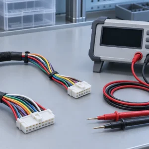


HARNESS QUALITY / MECHANICAL ACCEPTANCE
Crimp pull force checks the wire-to-terminal attachment. Terminal retention checks whether the terminal stays inside its housing. You need separate acceptance requirements because either connection can fail independently. Define the components, test setup and limits before approving production.
What Does Each Test Actually Check?
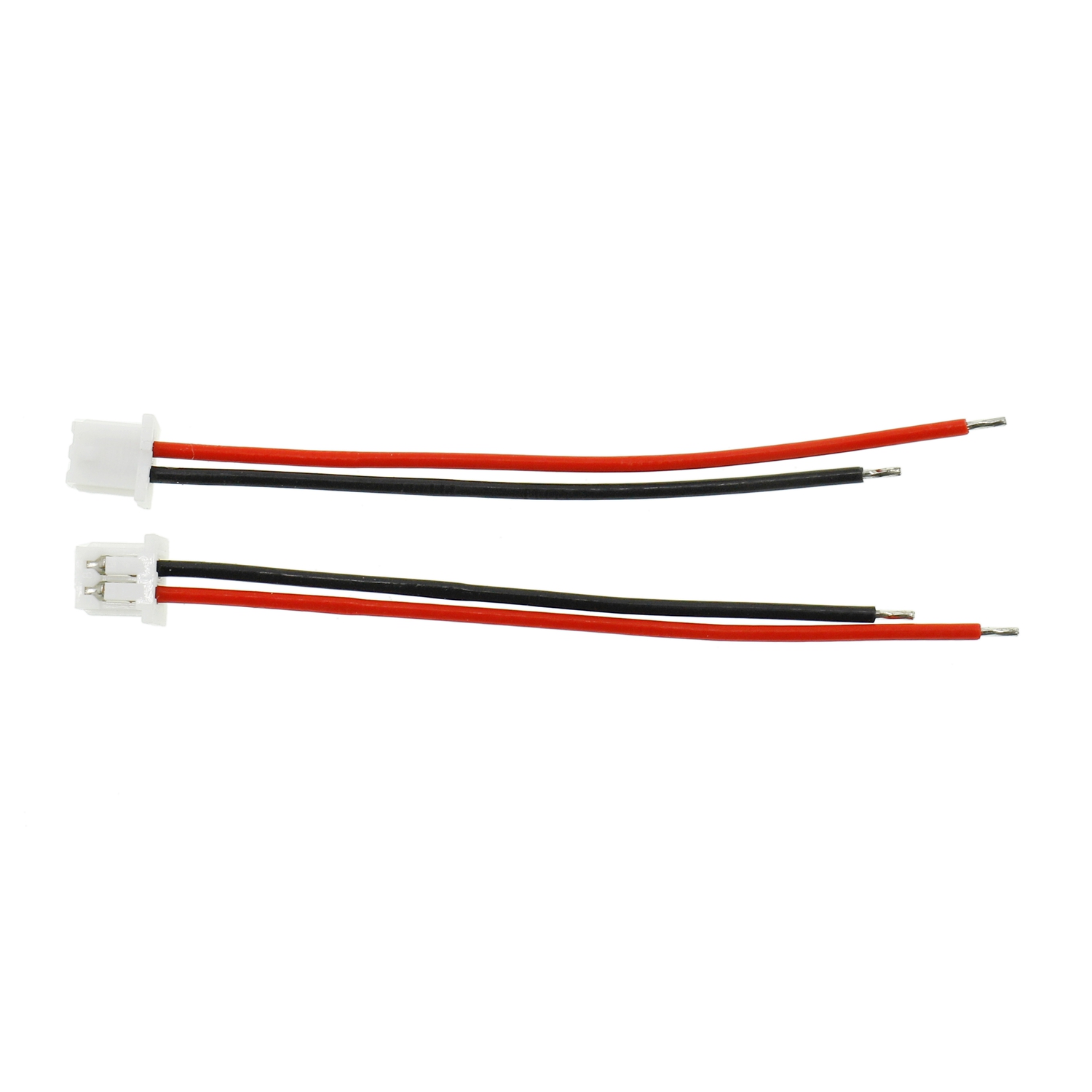
You test different interfaces when you measure crimp pull force and terminal retention.
For a crimp pull test, you evaluate the attachment between the conductor and its crimped terminal. The specified preparation determines whether insulation support contributes to the result.
For terminal retention, you evaluate the terminal’s restraint inside the housing. Your fixture must load that interface without confusing another failure with terminal release.
| Check | Interface Evaluated | What It Does Not Establish |
|---|---|---|
| Crimp pull force | Wire attachment to the terminal | Terminal locking inside the housing |
| Terminal retention | Terminal restraint inside the housing | Acceptable conductor crimp geometry |
| Connector unmating force | Separation of the mating connector halves under the stated conditions | Individual terminal retention |
| Electrical continuity | A conductive path under the electrical test conditions | Mechanical retention under a specified load |
Molex lists terminal retention as a distinct mechanical check in its Micro-Lock Plus product specification. That document applies to its stated connector system. You should not transfer its limits to another family.
Why Can A Strong Crimp Still Back Out?
A sound wire-to-terminal attachment cannot compensate for an incorrectly retained terminal.
You may have the wrong contact, incomplete insertion or damaged locking features. Check the approved contact and housing combination before changing the crimp settings.
Primary retention features restrain terminals within their housings. Some connector systems also use terminal position assurance, often abbreviated TPA.
Connector position assurance, or CPA, acts at the mating connector interface. You cannot treat CPA and TPA as interchangeable checks.
Use the connector family’s assembly instructions because locking arrangements vary. Molex explains these distinctions in its connector contact retention guide.
For your incoming inspection, request evidence tied to the actual part numbers. A generic photograph of a locked connector cannot confirm your assembly’s condition.
How Should You Specify Crimp Pull Force?
You should define crimp pull acceptance using the applicable terminal, wire and processing documentation.
Record the terminal reference, conductor construction, wire size and relevant insulation dimensions. Identify the approved tooling and specification revision.
Also define sample preparation, gripping, loading direction and test speed. State whether the method requires insulation support to be disabled.
Molex directs users to its application tooling specifications for crimp height, pull force and strip length. Use the document applicable to your combination.
Do not select an acceptance force from wire gauge alone. A numerical requirement without its test method is incomplete.
How Should You Specify Terminal Retention?
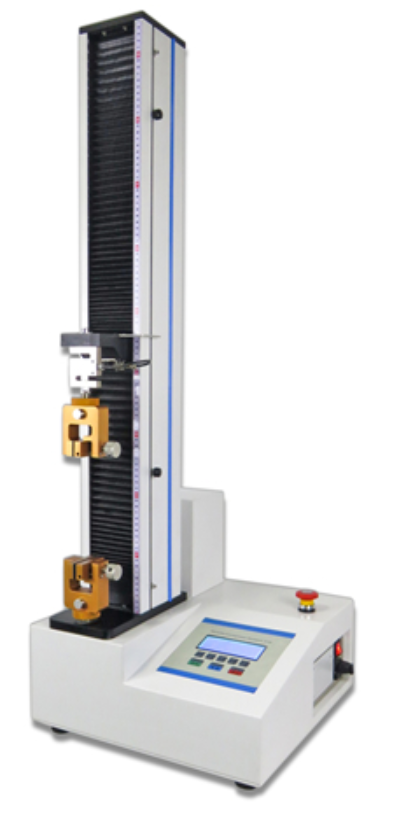
You should define terminal retention using the exact housing, contact and locking configuration.
Identify the loaded cavity and terminal orientation. State whether secondary locks are engaged and how the housing is supported.
Record the loading axis, speed, force requirement and inspection after loading. Clarify whether you need a proof-load check or a destructive qualification test.
A wire breaking first does not measure terminal release force. Record that failure mode and review whether the setup answers your intended question.
For any destructive method, identify the specimens and their disposition. Do not return damaged or unapproved tested samples to shipment.
A manual insertion check is different from qualification testing. Use only the manufacturer-approved check; do not invent a universal tug force.
What Should The Supplier’s Test Record Include?
Your test record should connect each result to a component combination and an agreed method.
- Assembly drawing number and revision
- Wire, contact and housing part numbers
- Sample identity and production lot
- Test type and governing document revision
- Preparation, fixture and gripping details
- Lock condition, loading direction and speed
- Acceptance limit, measured result and units
- Failure location and pass/fail decision
- Equipment identification and calibration status
- Sampling frequency and tested-sample disposition
You can compare results only when their boundaries match. Keep terminal retention and conductor crimp results in separately identified fields.
Also verify cavity assignments through connector pinout verification. A securely retained terminal can still occupy the wrong cavity.
How Do You Investigate A Failed Result?
You should investigate the failure location before changing components or process settings.
| Observation | Review First |
|---|---|
| Conductor slips from the crimp | Wire/contact compatibility, strip preparation, tooling and specified crimp dimensions |
| Terminal leaves the housing | Contact reference, insertion depth, retention features and lock condition |
| Wire breaks before terminal release | Whether the load path and specimen can evaluate the required retention criterion |
| Mating connector halves separate | Whether you are evaluating connector locking rather than individual terminal retention |
Contain affected material according to your quality plan. Retain failed specimens and record the cavity, orientation and observed damage.
Use approved extraction and repair instructions when rework is allowed. Confirm whether the affected terminal or housing needs replacement.
JST’s handling precautions reinforce component-specific processing and handling. Your repair route must follow the selected connector’s documentation.
What Can XSD Review For Your Harness?
XSD can review crimping, connector assembly and selected mechanical inspection requirements against your approved design.
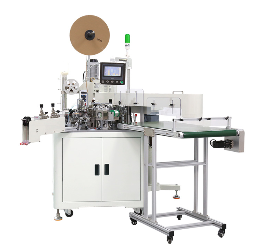
XSD’s documented manufacturing capabilities include terminal processing, connector insertion and tensile inspection resources. Review the required retention fixture and method separately.
Provide actual component references when requesting JST cable assemblies or Molex cable assemblies. Brand names alone do not define the test.
Fixture development, destructive samples, connector variants and reporting requirements affect quotation scope. Separate these requirements from routine assembly quantities.
Frequently Asked Questions
You need separate mechanical criteria when your specification requires both crimp strength and terminal retention.
Does A Passed Crimp Pull Test Prove Terminal Retention?
No. You evaluated the wire-to-terminal attachment, not the terminal’s restraint inside its housing.
Does Continuity Prove The Terminal Is Locked?
No. An electrical path can exist before the assembly experiences the mechanical load you need to evaluate.
Can You Use One Pull Force For Every Connector?
No. Use the applicable component documentation and agreed test method for each approved combination.
Should You Pull Every Finished Wire To Failure?
No. Distinguish approved production checks from destructive sampling. Define the sampling plan and disposition before testing.
Define Both Checks Before You Order
You should send the drawing, component BOM, wire specification, test documents, sampling plan and reporting needs. Include sample quantities and forecast demand. Contact us for a harness manufacturing review before releasing your acceptance requirements.