

Verify your connector pinout against the exact component drawing, viewing direction and connection table before releasing a harness. A clear photograph cannot replace cavity identification. Your assembly instructions and electrical test must reference the same approved circuit map.
Why Can The Same Connector Pinout Look Reversed?
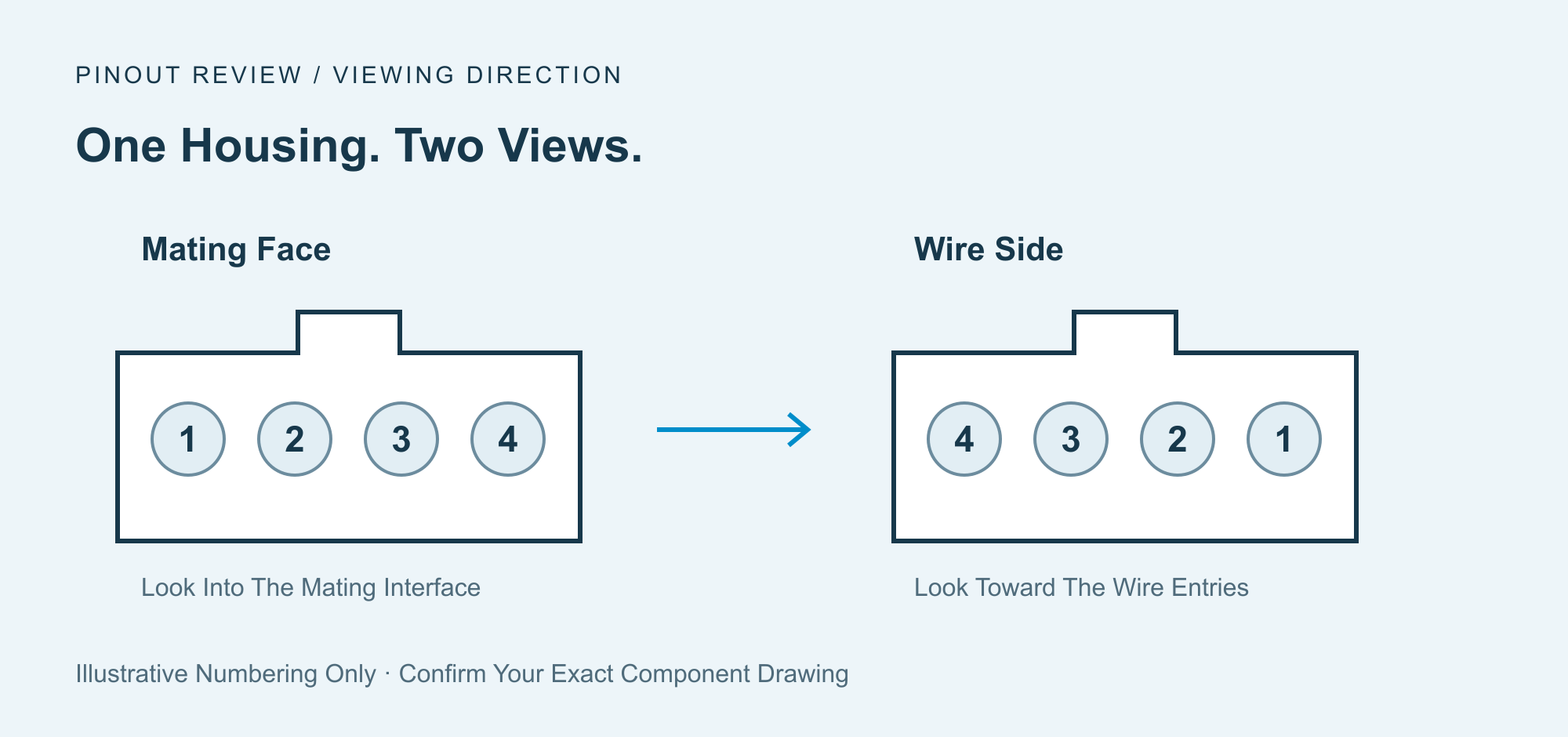
Your cavity positions can appear reversed when you move from the mating face to the wire-entry side.
The mating face looks toward the interface that joins the other connector. The wire side looks toward the cable entries. You must also specify which latch, key or reference feature faces upward.
A rotation can change the apparent arrangement again. Write the viewing direction beside each connector view. Mark cavity one and a physical orientation feature.
For broader documentation requirements, see our wire harness design guide. Here, the task is narrower: make each electrical endpoint unambiguous.
Which Drawing Should Control Cavity Identification?
Use the manufacturer drawing for your exact connector part number, then reference it in your approved harness documentation.
Confirm housing identity, circuit count, keying variant and mating counterpart. Similar shells do not establish identical numbering or circuit assignments.
Molex explains polarization and keying as distinct features controlling mating orientation and compatibility. Neither feature specifies your equipment’s signal assignments.
Do not apply a familiar counting pattern to an unfamiliar connector. Cirris documents several pin-counting sequences, including alternating and column arrangements.
- Record the connector part number and drawing revision.
- Identify whether the view shows the housing, mating counterpart or PCB footprint.
- Retain manufacturer cavity identifiers, including letters where used.
- Resolve drawing and sample conflicts before approving production.
What Should Your Connector Pinout Table Include?
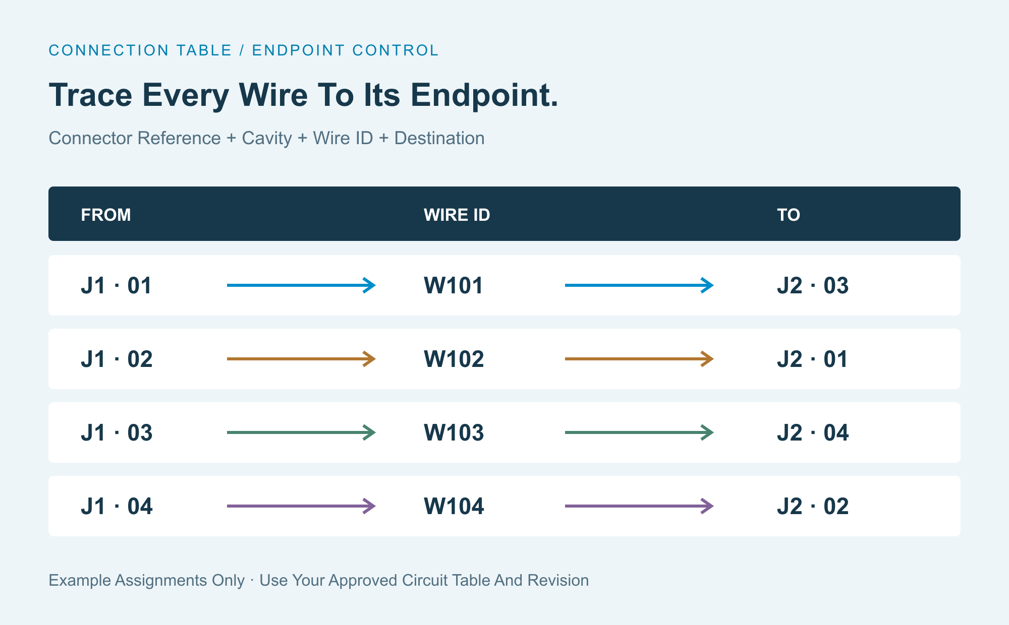
Your pinout table should identify both endpoints, the circuit function and the wire identification for each connection.
Separate electrical connectivity from physical appearance. A color helps an assembler find a wire; it does not replace a cavity reference.
| Field | What You Define | Why You Need It |
|---|---|---|
| Connector Reference | J1, J2 or your approved designation | Separates repeated connector types |
| Component Identity | Housing and contact part numbers | Connects the circuit map to the BOM |
| From / To Cavity | Exact identifiers at both endpoints | Defines the required connection |
| Circuit Function | Your power, return or signal designation | Supports engineering review |
| Wire Identity | Wire specification, color and printed ID | Controls material and identification |
| Special Connections | Splice, shield, drain or unused position | Prevents missing or unintended connections |
| Release Reference | Drawing and connection-table revision | Keeps assembly and inspection aligned |
If one circuit joins several endpoints, document the complete net. Do not force a splice into an incomplete one-to-one table.
How Do You Check A Pinout Before Production?
Check the component view, circuit table and physical sample against one approved release.
- Confirm the parts. Match each connector reference to its BOM item and mating component.
- Fix the viewpoint. Label the mating face or wire side, cavity one and orientation feature.
- Trace each circuit. Compare every endpoint with the schematic and connection table.
- Check exceptions. Include splices, shields, drain wires and unused positions.
- Review the first article. Compare the physical assembly and wire labels with the approved documents.
- Release the test definition. Verify the test program and fixture mapping before accepting batch results.
For an early build, our prototype wiring harness service provides a route to project review. Agree the sample scope and acceptance criteria first.
Why Is A Passing Continuity Test Not Enough?
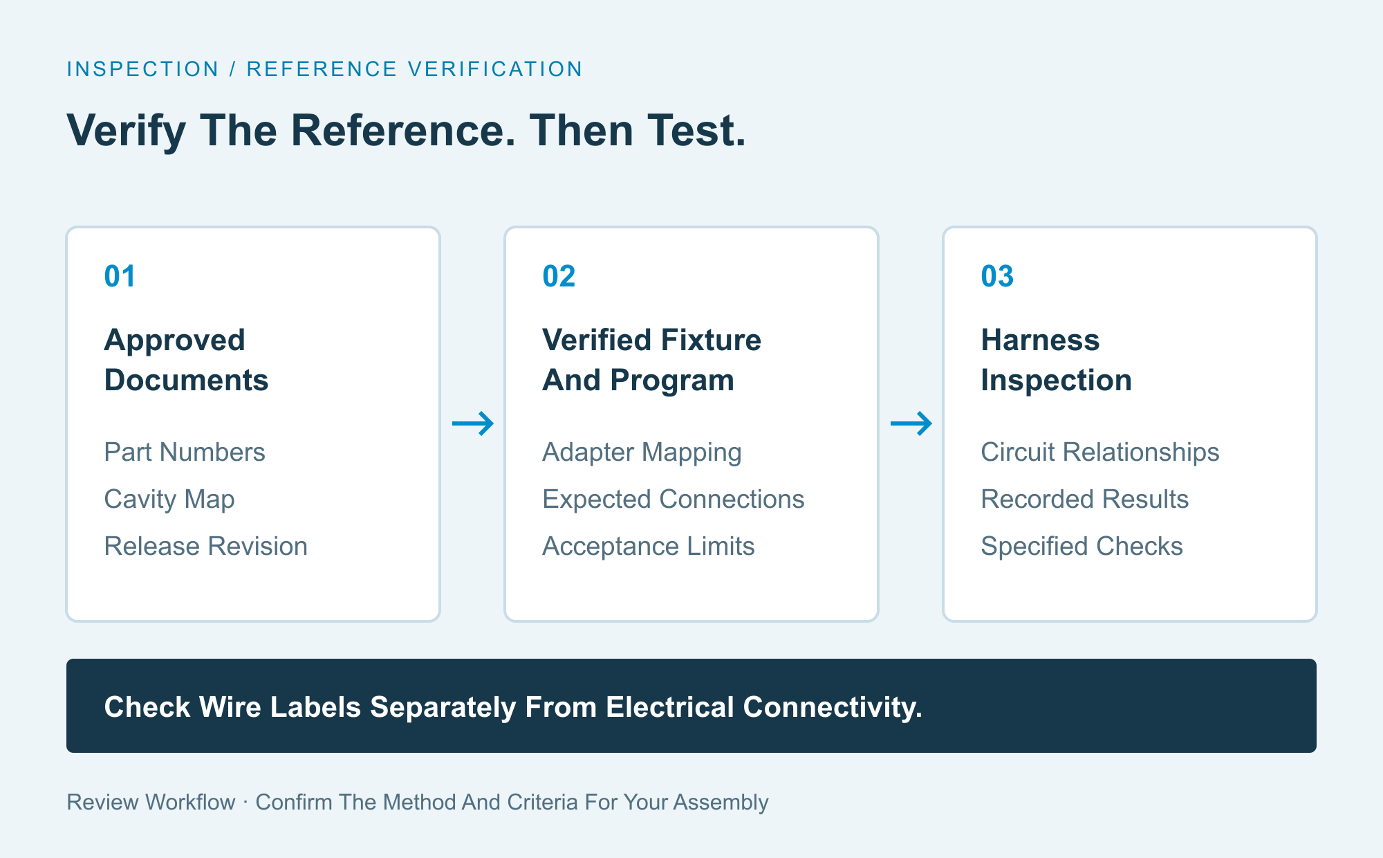
A passing continuity result supports your pinout only when the test definition correctly represents the approved assembly.
A tester can compare production against an incorrect reference. Learning a sample does not independently prove that sample’s circuit assignments.
Cirris recommends verifying test programs before testing. Compare learned connections and test parameters with assembly documentation. Confirm adapter mapping too.
Wire identification needs its own check. Cirris also distinguishes continuity from wire-label verification. Correct endpoint connectivity can coexist with incorrect wire IDs.
Specify expected connections, prohibited connections and acceptance limits. Continuity alone does not establish signal integrity, sealing or service life. Add relevant checks through your agreed harness inspection plan.
What Increases Pinout Verification Cost?
Your verification effort grows with ambiguous inputs, circuit complexity, fixture requirements and revision changes.
Repeated connector types need clear reference labels. Splices require complete net definitions. Shields and embedded components may need additional instructions.
A late circuit change can affect assembly instructions, fixtures and test programs. Freeze the approved revision before requesting repeat production.
Send prototype quantity, expected annual demand and documentation requirements for a project quotation. There is no universal verification fee or turnaround.
How Can XSD Support Your Pinout Review?
XSD manufactures harnesses from customer-approved drawings, BOMs and inspection requirements.
Our documented manufacturing capabilities include connector assembly, labeling and wire-sequence inspection resources. The process and acceptance criteria depend on your assembly.
You retain responsibility for approving the equipment’s circuit design. Manufacturing review does not replace system-level electrical validation. Confirm the available inspection method and reporting scope for your project.
Frequently Asked Questions About Connector Pinout Verification
Resolve these documentation questions before you release your connector pinout for a quotation or production.
Are Mating-Face And Wire-Side Views The Same?
No. They look from opposite directions. Label the viewpoint and orientation feature on each drawing.
Does Cavity One Always Start At The Upper Left?
No. Use your exact connector drawing. Numbering conventions and orientations vary between component families.
Can Wire Color Define The Pinout?
Color can support identification. You still need connector references, cavity identifiers and a complete connection table.
Does A Keyed Connector Prevent A Wrong Pinout?
No. Keying controls mating compatibility. You can still assign a wire to an incorrect cavity within a compatible housing.
Can You Verify A Pinout From A Photograph?
A photograph helps identify orientation. Hidden cavities, unreadable marks and uncertain component identities prevent it from replacing controlled documentation.
Should You Include Unused Positions?
Yes. Identify positions that remain unconnected. Specify any required sealing plugs separately for sealed connector systems.
Can A Sample Replace An Approved Connection Table?
Use a sample as supporting evidence. Confirm its connections and release the intended circuit map before repeat manufacturing.
What Changes Require Another Review?
Review changes to endpoints, connector variants, wire IDs, splices or test fixtures. Assess their effect before releasing another batch.
Send Your Connector Pinout For Review
Send your connector drawings, BOM, circuit table, labeled views and test requirements. Include prototype quantity and annual demand. Contact us to review manufacturing inputs before quotation.

