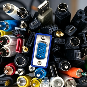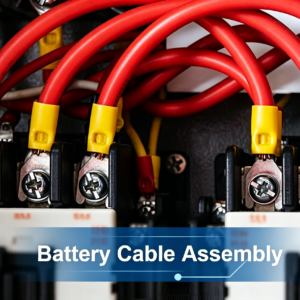

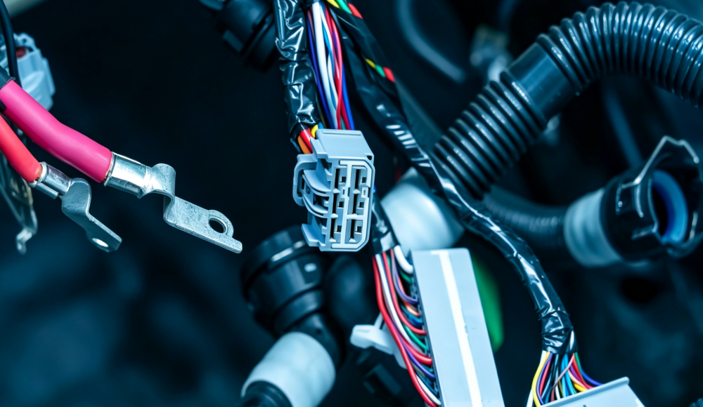
A well-designed wire harness considers wire selection, connectors, terminals, routing, wire length, protection, strain relief, testing, and design for manufacturing (DFM) from the beginning.
This guide explains the basics of electrical wire harness design, the key design steps, common mistakes to avoid, and practical advice for engineers, OEMs, and product developers preparing a harness for prototype or production.
What Is Electrical Wire Harness Design?
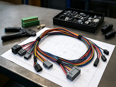
Electrical wire harness design is the process of defining the wires, cables, terminals, connectors, protective components, routing, and assembly requirements needed to create a functional electrical interconnection system.
A wire harness can distribute power, transmit signals, connect sensors, link control modules, or connect multiple electrical components within a machine or vehicle.
A professional wire harness design needs to achieve three objectives:
- Electrical performance— the harness must carry the required current, voltage, and signals.
- Mechanical reliability— the harness must withstand bending, vibration, temperature, abrasion, and other application conditions.
- Manufacturability— the design must be practical to assemble, test, inspect, and produce consistently.
A design that satisfies only the electrical requirements may still cause problems during installation or manufacturing.
What Information Is Needed for Wire Harness Design?
Before designing or manufacturing a custom wire harness, engineers should establish the basic technical requirements.
Wiring Diagram
The wiring diagram defines how individual circuits connect.
It may identify:
- Circuit functions
- Wire connections
- Pin assignments
- Power and ground connections
- Sensors and devices
- Connector interfaces
Bill of Materials (BOM)
A harness BOM normally identifies the components required for assembly, such as:
- Wires
- Terminals
- Connectors
- Seals
- Clips
- Sleeves
- Heat-shrink tubing
- Protective tubing
- Labels
Electrical Requirements
Important parameters include:
- Voltage
- Current
- Wire gauge
- Signal type
- Number of circuits
- Shielding requirements
- Electrical testing requirements
Mechanical Requirements
The design should also define:
- Overall harness dimensions
- Wire lengths
- Branch locations
- Connector orientation
- Mounting points
- Available installation space
- Bend radius
- Routing requirements
Environmental Requirements
Consider the actual operating environment, including:
- Temperature
- Vibration
- Moisture
- Dust
- Chemicals
- Oil
- Abrasion
- UV exposure
- Repeated flexing
Production Requirements
For a production project, also establish:
- Prototype quantity
- Annual or monthly volume
- Required certifications
- Inspection requirements
- Packaging requirements
- Production testing
The more complete the input information, the more accurately a manufacturer can evaluate the design and prepare a quotation.
What Are the Basics of Electrical Wire Harness Design?
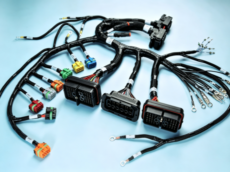
A wire harness consists of multiple components that must work together. The most important design decisions usually involve wires, terminals, connectors, wire lengths, and circuit routing.
Wire Selection
Wire selection should be based on the actual electrical and environmental requirements.
Consider:
- Wire gauge
- Current capacity
- Voltage rating
- Insulation material
- Temperature rating
- Flexibility
- Environmental resistance
- Shielding requirements
Choosing a wire only according to current capacity is not enough. Temperature, installation conditions, mechanical movement, and insulation requirements can also affect the appropriate wire specification.
Terminal Selection
The terminal creates the electrical and mechanical connection between the wire and connector.
The terminal should be compatible with:
- Wire size
- Conductor type
- Connector system
- Required current
- Crimping method
- Environmental requirements
Crimp quality is particularly important because a poor crimp can increase electrical resistance or reduce mechanical retention.
Connector Selection
Connector selection should consider:
- Number of circuits
- Current and voltage
- Connector size
- Mating requirements
- Locking mechanism
- Environmental protection
- Installation space
- Required mating cycles
The connector also influences harness routing and the physical design of the final assembly.
Wire Length
Wire length should provide enough allowance for installation without creating unnecessary excess.
Too short: The harness may be difficult to install or may place stress on connectors and terminals.
Too long: Excess wire can increase material cost, weight, routing complexity, and assembly time.
Wire length should therefore be determined from the actual installation path and mechanical requirements.
Branches and Circuits
Complex harnesses often include multiple branches.
Branch locations should be positioned according to:
- Connected components
- Installation points
- Routing requirements
- Assembly sequence
- Protection requirements
Poorly positioned branches can make both installation and manufacturing more difficult.
How to Design an Electrical Wire Harness Step by Step
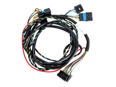
A practical wire harness design process can be divided into several stages.
Step 1: Define Electrical Requirements
Start by identifying:
- Voltage
- Current
- Circuit functions
- Signal requirements
- Number of circuits
- Grounding requirements
- Protection requirements
These requirements establish the foundation for wire and component selection.
Step 2: Create or Review the Wiring Diagram
The wiring diagram should clearly show how the electrical system is interconnected.
Review:
- Connector pinouts
- Circuit numbers
- Wire connections
- Power circuits
- Ground circuits
- Signal circuits
Before moving into physical harness design, make sure the electrical architecture is clearly defined.
Step 3: Select Wires and Cables
Select the appropriate wire according to:
- Gauge
- Current
- Voltage
- Insulation
- Temperature
- Flexibility
- Environmental requirements
For applications involving repeated movement, flexibility and bending performance may become particularly important.
Step 4: Select Terminals and Connectors
Choose compatible terminals and connectors based on the electrical and mechanical requirements.
Verify:
- Wire compatibility
- Terminal compatibility
- Connector pin configuration
- Current and voltage ratings
- Environmental requirements
- Mechanical retention
Step 5: Determine Cable Lengths
Determine the required length for each wire or cable branch based on the actual installation path.
Allow for:
- Connector positioning
- Bending
- Routing
- Branching
- Manufacturing tolerances
- Installation requirements
Step 6: Design Routing and Branching
Plan the physical routing of the harness.
Consider:
- Moving parts
- Hot surfaces
- Sharp edges
- Vibration
- Available space
- Mounting points
- Service access
The harness should follow a controlled routing path rather than simply filling available space.
Step 7: Add Protection
Depending on the application, the harness may require:
- Corrugated tubing
- Braided sleeving
- Heat-shrink tubing
- Spiral wrap
- Protective conduit
- Grommets
- Clips
- Cable ties
Protection should be selected according to the actual mechanical and environmental risks.
Step 8: Create the Harness Drawing and BOM
A production-ready documentation package should clearly define:
- Wire specifications
- Wire lengths
- Connector part numbers
- Terminal part numbers
- Branch dimensions
- Protection materials
- Labels
- Assembly requirements
A clear drawing and BOM reduce ambiguity between engineering, purchasing, and manufacturing.
Step 9: Review for Design for Manufacturing
Before production, review the design from the manufacturer’s perspective.
Ask:
Can this harness be assembled, crimped, tested, inspected, and produced consistently?
This review can identify problems before tooling or mass production.
Step 10: Prototype and Test
A prototype allows engineers to verify:
- Electrical performance
- Physical fit
- Routing
- Connector orientation
- Installation
- Mechanical clearance
- Testing procedures
Design changes are usually easier and less expensive to make during the prototype stage than after mass production begins.
What Is Design for Manufacturing (DFM) in Wire Harness Design?
Design for Manufacturing (DFM) means designing a wire harness so that it can be manufactured efficiently, consistently, and reliably.
A harness can be electrically correct but still be difficult to produce.
Consider Assembly Operations
The design should accommodate actual manufacturing processes such as:
- Wire cutting
- Stripping
- Crimping
- Terminal insertion
- Connector assembly
- Bundling
- Labeling
- Testing
Consider Crimp Accessibility
Terminals must be compatible with the required wire size and crimping process.
If the design requires unusual or difficult crimping operations, manufacturing complexity can increase.
Optimize Wire Length
Wire lengths should provide sufficient installation allowance without unnecessary excess.
This can help control:
- Material consumption
- Harness size
- Assembly complexity
- Installation difficulty
Consider Branch Locations
Branch points should be positioned to support both installation and assembly.
An awkward branch location can increase assembly time or create routing problems.
Consider Connector Orientation
Connector orientation affects:
- Product installation
- Harness routing
- Operator assembly
- Mechanical stress
The orientation should be defined clearly in the drawing.
Design for Testing
The finished harness should be compatible with the required inspection and testing processes.
Depending on the application, this may include:
- Continuity testing
- Short-circuit testing
- Insulation testing
- Hi-pot testing
- Pin-to-pin verification
- Mechanical inspection
Standardize Components Where Practical
Using common or proven components where application requirements allow can simplify:
- Procurement
- Inventory
- Assembly
- Quality control
- Replacement
However, component standardization should never override electrical, mechanical, or environmental requirements.
How Does the Operating Environment Affect Wire Harness Design?
A harness that performs well in a laboratory may not perform the same way in a vehicle, robot, or industrial machine.
The operating environment should therefore be considered during the initial design stage.
Temperature
Consider both normal operating temperature and potential temperature extremes.
Temperature affects:
- Wire insulation
- Connector materials
- Terminal performance
- Protective materials
- Long-term reliability
Vibration
Vibration can affect:
- Crimp connections
- Connector retention
- Wire insulation
- Mounting points
- Branch areas
Automotive, industrial, and machinery applications may require particular attention to vibration.
Moisture and Water
If the harness is exposed to moisture, the design may require appropriate:
- Sealed connectors
- Cable protection
- Grommets
- Environmental sealing
The required environmental protection should be defined according to the actual application.
Abrasion
Wires routed near metal edges or moving components may require additional protection.
Possible solutions include:
- Sleeving
- Conduit
- Protective tubing
- Grommets
- Controlled routing
Chemicals and Oils
For industrial or automotive environments, materials should be evaluated for compatibility with expected exposure to oils, cleaning agents, chemicals, or other substances.
UV Exposure
Outdoor applications may require materials with appropriate resistance to UV exposure.
Repeated Flexing
Robotic and moving applications can expose harnesses to repeated bending.
In these applications, consider:
- Flexible cable construction
- Bend radius
- Routing
- Strain relief
- Repeated-motion requirements
What Are the Most Common Wire Harness Design Mistakes?
Even experienced engineers can encounter harness problems when electrical, mechanical, and manufacturing requirements are considered separately.
Here are some common mistakes to avoid.
1. Selecting the Wrong Wire Gauge
An inappropriate wire gauge can affect electrical performance and thermal behavior.
Advice: Select wire based on current, voltage, temperature, installation conditions, and applicable requirements.
2. Ignoring Temperature Requirements
A wire or connector suitable for one environment may not be suitable for another.
Advice: Consider the complete operating temperature range when selecting materials and components.
3. Choosing the Wrong Connector
Connector selection affects electrical performance, mechanical retention, installation, and environmental protection.
Advice: Match the connector to the electrical, mechanical, environmental, and space requirements.
4. Making Wires Too Short
Short wires can create tension during installation.
Advice: Determine length from the actual routing path and allow appropriate installation tolerance.
5. Making Wires Excessively Long
Excessive length increases material usage and may make installation more difficult.
Advice: Optimize wire length according to the actual application.
6. Ignoring Bend Radius
Excessive bending can place mechanical stress on the wire and termination.
Advice: Consider the cable construction and required bending conditions during routing.
7. Poor Harness Routing
Routing a harness too close to heat sources, sharp edges, or moving components can reduce reliability.
Advice: Review the complete mechanical environment before finalizing the routing.
8. Insufficient Strain Relief
Mechanical forces can concentrate around connector and terminal transitions.
Advice: Use appropriate strain relief, mounting, and routing strategies.
9. Poor Terminal or Crimp Selection
A terminal must match the wire and connector system.
Advice: Confirm terminal compatibility and define the required crimping process.
10. Designing Without Manufacturing in Mind
A technically functional design may still be difficult to assemble or test.
Advice: Conduct a DFM review before tooling or mass production.
11. Inadequate Testing Requirements
If testing requirements are not defined early, validation may become more difficult later.
Advice: Establish electrical, mechanical, dimensional, and functional testing requirements before production.
12. Skipping Prototype Validation
A harness can look correct in a drawing but behave differently during actual installation.
Advice: Prototype and test critical designs before committing to mass production.
How Do You Validate an Electrical Wire Harness Design?
Validation should cover electrical, mechanical, dimensional, and functional requirements.
Electrical Testing
Depending on the application, testing may include:
- Continuity
- Short-circuit detection
- Insulation resistance
- Hi-pot / dielectric withstand
- Pin-to-pin verification
Mechanical Testing
Potential mechanical checks include:
- Terminal retention
- Connector retention
- Pull force
- Flexing
- Vibration
The appropriate tests depend on the application and customer requirements.
Dimensional Validation
Check:
- Overall harness length
- Branch dimensions
- Connector orientation
- Mounting points
- Protection components
Functional Validation
Finally, verify that the harness performs correctly when installed in the intended system.
This can identify problems that may not be visible during individual component testing.
What Should a Wire Harness Drawing and BOM Include?
Clear documentation is essential when a custom wire harness moves from engineering to production.
Harness Drawing
A drawing may include:
- Overall dimensions
- Wire lengths
- Branch locations
- Connector orientation
- Protection components
- Mounting components
- Labels
- Assembly requirements
BOM
The BOM should identify relevant components, such as:
| Component | Typical Information |
| Wire | Part number, gauge, color, specification |
| Terminal | Part number, compatible wire range |
| Connector | Manufacturer and part number |
| Seal | Part number and compatibility |
| Protection | Material and size |
| Clip | Part number and mounting requirements |
| Label | Marking requirements |
Wiring / Pinout Information
Clearly define:
- Circuit number
- Pin number
- Wire color
- Wire gauge
- Connection information
Revision Control
For production projects, maintain:
- Drawing revision
- Revision date
- Engineering change description
- Approved documentation
Good revision control helps prevent outdated designs from entering production.
What Factors Affect Wire Harness Manufacturing Cost?
Custom wire harness pricing depends on the complete assembly rather than simply the number of wires.
Major cost factors include:
- Wire type
- Wire gauge
- Wire length
- Connector costs
- Terminal costs
- Protection materials
- Number of circuits
- Crimping requirements
- Assembly complexity
- Testing requirements
- Tooling or fixtures
- Production volume
- Packaging
- Special certifications or inspection requirements
Production quantity can also significantly affect the overall unit cost.
For an accurate quotation, a manufacturer will typically need the drawing, BOM, specifications, quantity, and application requirements.
When Should You Ask a Wire Harness Manufacturer to Review Your Design?
It is often beneficial to involve a wire harness manufacturer before mass production, and for complex projects, even during the design stage.
A manufacturing review can identify potential problems such as:
- Difficult crimping operations
- Incorrect terminal selection
- Difficult assembly sequences
- Excessive wire lengths
- Poor branch geometry
- Connector orientation issues
- Testing challenges
- Component availability
- Potential cost drivers
Early DFM feedback can reduce the risk of redesigning the harness after tooling or production has started.
For OEM projects, a practical workflow is:
Design → DFM Review → Prototype → Testing → Design Approval → Mass Production
What Should You Look for in a Wire Harness Manufacturer?
Choosing a wire harness supplier should involve more than comparing unit prices.
Engineering Capability
Ask whether the manufacturer can review:
- 2D drawings
- 3D models
- BOMs
- Wiring diagrams
- Samples
- Technical specifications
Wire Processing Capability
Relevant manufacturing processes may include:
- Automatic wire cutting
- Wire stripping
- Terminal crimping
- Terminal insertion
- Connector assembly
- Harness bundling
Testing Capability
Depending on the product, the manufacturer should be able to support appropriate electrical and mechanical testing.
Quality Management
Evaluate the supplier’s:
- Quality system
- Inspection procedures
- Process controls
- Traceability
- Testing records
Prototype to Mass Production
For OEM projects, it is advantageous if one manufacturer can support:
Prototype → Validation → Pilot Production → Mass Production
This can reduce supplier changes and simplify project management.
Custom Wire Harness Manufacturing Support from XSD Harness
XSD Harness specializes in custom wire harness and cable assembly manufacturing for applications where electrical performance, mechanical reliability, and production consistency are important.
A typical project can move through:
Customer Drawing / BOM / Sample
↓
Engineering Review
↓
Component & Process Evaluation
↓
Wire Processing
↓
Crimping & Connector Assembly
↓
Harness Assembly
↓
Electrical / Mechanical Testing
↓
Final Inspection
↓
Production & Delivery
For a custom project, customers can provide available technical information such as:
- 2D drawings
- 3D models
- BOMs
- Wiring diagrams
- Connector part numbers
- Terminal specifications
- Wire specifications
- Samples
- Required quantities
- Testing requirements
If your design is still under development, an engineering review can also help identify potential manufacturing issues before production.
FAQs About Electrical Wire Harness Design
What is electrical wire harness design?
Electrical wire harness design is the process of defining wires, terminals, connectors, routing, protection, and assembly requirements to create a reliable electrical interconnection system.
What are the basic steps in wire harness design?
The typical process includes defining electrical requirements, reviewing the wiring diagram, selecting wires and connectors, determining wire lengths, designing routing and branches, adding protection, creating drawings and BOMs, reviewing DFM, and validating a prototype.
How do I choose the correct wire gauge?
Wire gauge should be selected based on current, voltage, temperature, insulation, installation conditions, and other application requirements. Current capacity alone should not be the only consideration.
How do I select a wire harness connector?
Consider pin count, current, voltage, physical size, mating requirements, locking mechanism, environmental conditions, installation space, and required mechanical performance.
What factors affect wire harness design?
Major factors include electrical requirements, mechanical space, wire and connector selection, routing, wire length, temperature, vibration, moisture, abrasion, flexibility, protection, testing, and manufacturability.
What is DFM in wire harness manufacturing?
Design for Manufacturing, or DFM, means designing the harness so that it can be assembled, tested, inspected, and produced consistently and efficiently.
What are the most common wire harness design mistakes?
Common mistakes include incorrect wire selection, poor connector selection, improper wire length, excessive bending, poor routing, insufficient strain relief, unsuitable terminals, inadequate protection, and failure to consider manufacturing requirements.
How do you validate a wire harness design?
Validation may include continuity, short-circuit, insulation, Hi-pot, terminal retention, pull, dimensional, functional, and application-specific testing.
What should a wire harness drawing include?
A production drawing may define wire lengths, branch locations, connector orientation, wire specifications, protection components, labels, mounting components, and assembly requirements.
What information does a manufacturer need to quote a custom wire harness?
A manufacturer will typically need a drawing, BOM, wiring diagram, wire specifications, connector and terminal information, quantity, application requirements, and testing specifications when applicable.
Can a wire harness manufacturer review my design before production?
Yes. A manufacturer with engineering and production experience can review drawings, BOMs, wiring diagrams, or samples for manufacturability and identify potential issues before production.