New Product Development
Validate the electrical architecture with an initial engineering sample.

Engineering samples for fit, function and manufacturing review before production release.
XSD Harness manufactures prototype wiring harnesses for engineering validation, fit and function checks, first-article approval, pilot builds, and pre-production testing. We can work from customer drawings, wiring diagrams, BOMs, connector specifications, or existing samples.
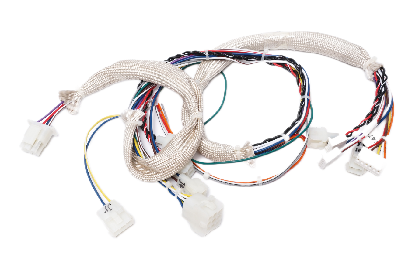
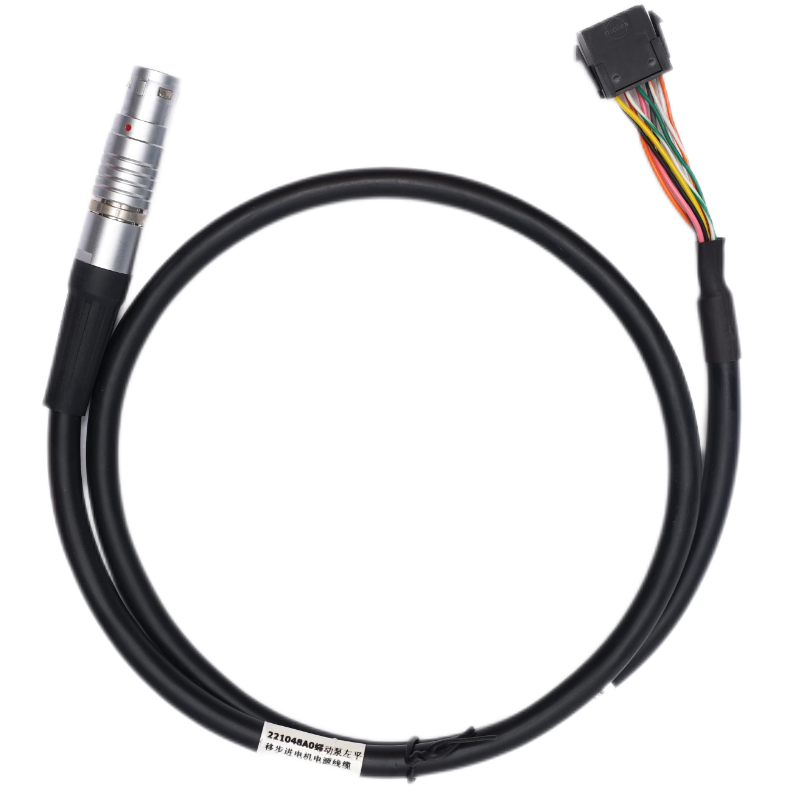
Assembly examples · Illustrative layout
A prototype wiring harness is an early manufacturing build used to verify electrical connections, connector selection, dimensions, branch routing, mechanical fit, protection methods and assembly requirements before full production. It helps identify design or manufacturability issues while changes can still be made with less disruption.
XSD can manufacture prototype wire harnesses from approved drawings, wiring diagrams, BOMs, connector part numbers, samples and inspection requirements.
Validate the electrical architecture with an initial engineering sample.
Review a changed connector, terminal, wire, sensor or mating device.
Check branch lengths, routing, clip positions and connector orientation in equipment.
Verify pinout, polarity, continuity or circuit logic before production.
Physically evaluate protection, sleeving, sealing or molding requirements.
Evaluate a controlled small batch before final production release.
Review an existing harness where the manufacturing package is incomplete.
| Area | Prototype build | Production build |
|---|---|---|
| Primary goal | Validate design and manufacturability | Repeatable volume manufacturing |
| Quantity | Low-volume / sample quantity | Production quantity |
| Design status | May still change | Released / controlled |
| Tooling | Minimal or temporary where feasible | Production fixtures / tooling as required |
| Documentation | Engineering-focused | Production-controlled |
| Components | Approved alternatives only if agreed | Approved BOM / component control |
| Inspection | Design and first-article verification | Defined production quality plan |
| Changes | Expected during iteration | Controlled engineering change process |
The more complete the engineering package, the faster XSD can evaluate component availability, manufacturing method and prototype feasibility.
Have an incomplete package? Share what is available and identify what still needs confirmation.
A sample helps explain construction. It does not replace an approved pinout, material definition or acceptance criteria.
Review the interfaces and assembly details before cutting the first wire. Resolve unclear requirements with the customer rather than assuming the design intent.
Match the housing, terminal, wire, seal and mating interface.
Check wire size and strip dimensions against the selected terminal.
Review reach, slack and tension at installation points.
Check whether the route suits the wire or cable construction.
Clarify keying, locks, cavity views and installation direction.
Locate sleeves, heat shrink, conduit, clips and boots.
Review space, geometry, materials and feasible tooling.
Agree electrical and mechanical acceptance criteria.
Review the drawing, BOM, pinout, sample, quantity and objectives.
Confirm wires, connectors, terminals, seals, sleeves and labels.
Resolve sourcing, assembly, routing and inspection concerns.
Cut, strip, crimp, solder, insert, route, protect and assemble to the approved definition.
Perform the agreed electrical, dimensional, visual and mechanical checks.
Check fit, function, installation and application-specific criteria.
Incorporate approved dimension, component, routing or protection changes.
Convert the approved prototype into a controlled production build.
Processing is selected for the connector, terminal, design and prototype quantity—not every sample uses every operation.
Automatic cutting and stripping to prototype dimensions.
Automatic or semi-automatic terminal processing, as appropriate for the specified connection.
Terminal insertion and cavity configuration according to the approved pinout.
Selected soldered interfaces; documented resources include RJ45 processing and HDMI soldering.
Heat shrink, tubing, sleeves, labels, tape, vertical injection molding, low-pressure molding or UV dispensing where appropriate.
Route and assemble to the drawing or agreed prototype fixture.
Confirm wire-to-terminal relationships.
Check according to the approved prototype inspection plan.
Confirm wire lengths, branch lengths and critical dimensions.
Use visual inspection, cross-section analysis or pull-force tests where required.
Check insertion, orientation, locks, seals and mating compatibility.
Agree critical dimensions, characteristics and required records.
Inspection methods depend on the prototype’s purpose and approved acceptance criteria. Not every prototype requires every available test. Prototype measurement and inspection records can be agreed during quotation; no standardized formal FAI package is implied.
Documented inspection resources also include wire sequence, DC resistance and CCD inspection, plus bending, salt-spray and plug/pull force equipment. Select methods against the project requirements.
Prototype quantities are reviewed according to harness complexity, component availability, tooling needs and production method. Simple assemblies may be feasible in very small quantities; special tooling or custom molding can require a different minimum build quantity.
Request the quantity you need. The feasible build quantity is confirmed for the project.
Prototype lead time is quoted after the BOM, component availability, build complexity and required inspections are reviewed.
Changes may cover wire length, branch routing, connector orientation, labels, protection, clips, wire gauge or approved component substitutions. Record each approved revision so the final production configuration can be frozen.
Illustrative revision sequence — not a customer project or approved drawing.
Record the prototype definition before assembly so evaluation refers to a known configuration.
Rev A → Build → Test → Feedback → Rev B → Approval → Production Release
Prototype schedules often depend more on connector and terminal availability than on assembly time. XSD can manufacture with customer-specified approved part numbers and review alternative sourcing options when requested. Substitutions must not be made without customer approval.
Record the approved manufacturer, part number and sourcing route. An alternative component needs its own compatibility and acceptance review.
Using the same supplier for samples and production can carry approved construction and inspection requirements into repeat manufacturing.
Confirm the final drawing, BOM, pinout, labels and materials.
Document critical processing and assembly requirements.
Define incoming, in-process and final inspection requirements.
Use dedicated assembly aids where repeatability requires them.
Run a controlled initial production batch where appropriate.
Move to agreed production quantities after approval.
Early-stage vehicle electronics, sensors, auxiliary systems and equipment.
Motors, encoders, sensors, controllers and experimental machine systems.
Prototype machine controls, instrumentation and automation wiring.
Battery, BMS, control and auxiliary harness validation.
Diagnostic or device interconnections to customer-defined requirements.
Machinery, control systems, sensors and field equipment.
Developmental interconnections for new devices.
Photos show assembly constructions, not documented prototype projects. High-voltage, molded and sealed designs require project-specific feasibility and validation review.
Prototype projects often contain unreleased product information. XSD can work under customer NDA requirements where agreed before project review. Drawings, BOMs, samples and technical information should be handled according to the applicable confidentiality agreement and internal project controls.
Support for initial engineering samples through repeat manufacturing.
Wire preparation, crimping, connector assembly, selected soldering, molding and harness assembly.
Wire and cable specification experience through Dongguan XSD Cable Technology Co., Ltd.
Electrical, dimensional, crimp and mechanical inspection equipment.
Review drawings, BOMs, pinouts, wire specifications, connector requirements and samples.
Automotive, industrial, energy, robotics, medical, agricultural and electronic applications.
Send the information available for review. If confidentiality terms are needed, agree them before uploading unreleased documents.
Optional preparation checklist — select the items you already have.
0 of 20 items ready
Send the drawing, wiring diagram, BOM, pinout, connector and terminal references, wire specification, dimensions, quantity, target date and inspection criteria. Include sample information if available. Missing details can be identified during review.
An existing sample can support manufacturing review and reconstruction of the build definition. Material specifications, pinout, dimensions, hidden connections and acceptance criteria still need customer confirmation before manufacture.
XSD can review component compatibility, wire preparation, routing, protection, molding feasibility and inspection requirements. Proposed changes require customer approval; the review does not replace the customer’s product-design responsibility.
Quantity is reviewed by project. Component order requirements, assembly complexity, tooling and process setup affect the feasible minimum. There is no universal no-MOQ commitment.
Lead time is quoted after reviewing the BOM, availability, build complexity, engineering clarifications, quantity and inspections. Provide your target prototype date so feasibility can be checked.
Yes, revisions can be reviewed after evaluation. Document approved changes and identify the drawing/BOM revision for each subsequent build. Schedule and cost effects should be agreed before rebuilding.
Prototype measurement and inspection records can be agreed during quotation. This page does not promise a standardized formal FAI, PPAP or AS9102 package. Send any required record format for review.
Specified part numbers can be reviewed subject to legitimate supply, availability and process compatibility. Brand references identify components, not an authorization claim. Alternatives need customer approval.
Selected designs can be reviewed with molding, sealing and protection requirements. Tooling, materials, connector systems and validation criteria determine feasibility. A molded feature alone does not establish an IP rating.
XSD can support transition to repeat manufacturing once the configuration, instructions, inspection plan and any fixtures or tooling are agreed. A pilot build may precede volume production.
Share the drawing, BOM, pinout or sample reference, your prototype quantity and your evaluation goals. Establish the build definition before moving to production.