
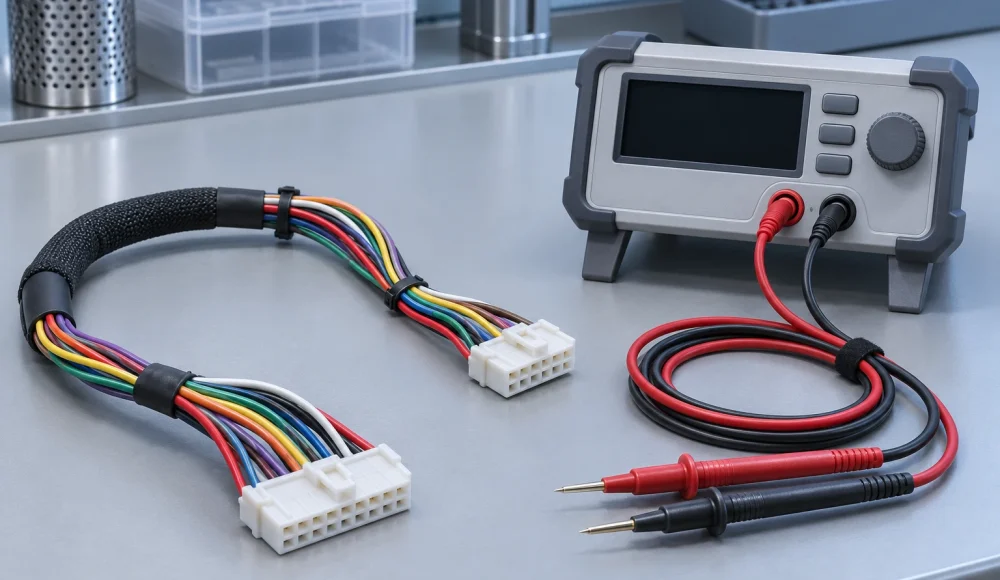
Your wire harness resistance test limit needs a defined circuit, measurement boundary and test method. A continuity pass alone does not establish suitability for operating current. Agree the resistance requirement with your supplier before approving samples or comparing quotations.
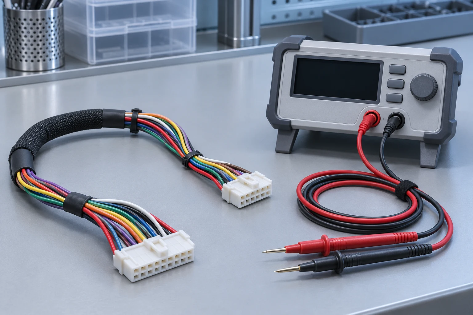
What Does A Resistance Test Limit Actually Accept?
A resistance limit accepts a specified electrical path under stated measurement conditions.
Start with the purpose. You might need circuit verification, an end-to-end resistance measurement or an assessment of one connection. These are different tasks.
| Requirement | Question You Answer | Information You Need |
|---|---|---|
| Continuity And Circuit Map | Are the intended points connected? | Approved netlist, thresholds and unintended connection checks |
| End-To-End Resistance | Is the defined path within its resistance limit? | Endpoints, included interfaces, conditions and method |
| Individual Connection Resistance | What resistance belongs to this specific connection? | Accessible measurement boundaries and component procedure |
| Operating Performance | Does the assembly meet its loaded application requirements? | Separate agreed electrical and thermal validation plan |
Cirris explains how test thresholds classify intended and unintended connections. Record the programmed settings instead of accepting an unexplained continuity label.
Where Does Your Measurement Start And Finish?
Your drawing should identify the exact endpoints and interfaces included in the reported resistance.
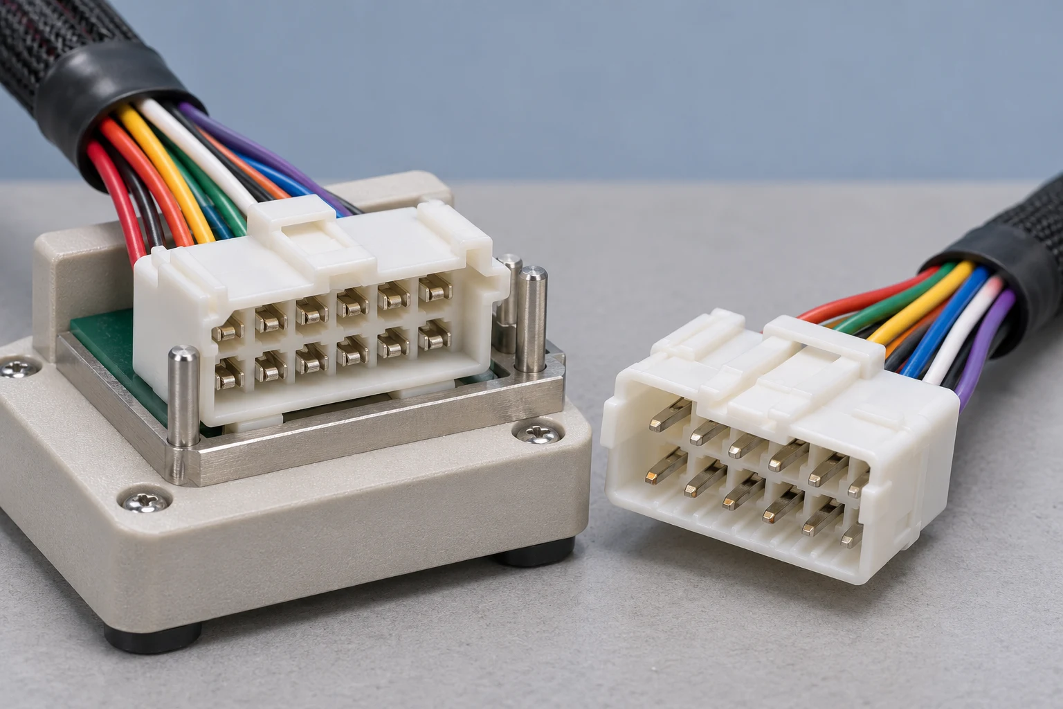
For example, define connector A cavity 1 to connector B cavity 4. State whether the measurement includes mating contacts, adapter wiring or another return conductor.
A loop measurement covers both the outgoing and return paths. Do not compare it directly with a single-conductor limit.
Review the connector viewing direction and cavity numbering before building the fixture. A precise resistance reading on the wrong circuit still answers the wrong question.
If you need one crimp evaluated separately, ask how the measurement will isolate it. An end-to-end result includes other contributions.
What Belongs In Your Resistance Budget?
Your resistance budget should distinguish product contributions from measurement-system effects.
Cirris identifies three practical considerations: assembly resistance, permitted product variation, and tester or fixture effects. Its resistance specification guidance explains why an unrealistically tight limit can reject conforming assemblies.
Use this as a review structure, not permission to increase a functional limit.
- Identify conductor material and the approved wire specification.
- Use the actual electrical path and permitted length range.
- Identify terminals, splices and mated interfaces within that path.
- Record the temperature conditions used for comparison.
- Assess fixture contributions and the instrument’s applicable accuracy.
Your product acceptance limit must still satisfy the application. If measurement capability cannot support it, improve the method or escalate the specification.
Do not derive production acceptance from one good sample. Use the engineering requirement and a measurement plan that addresses permitted variation.
When Should You Discuss Four-Wire Measurement?
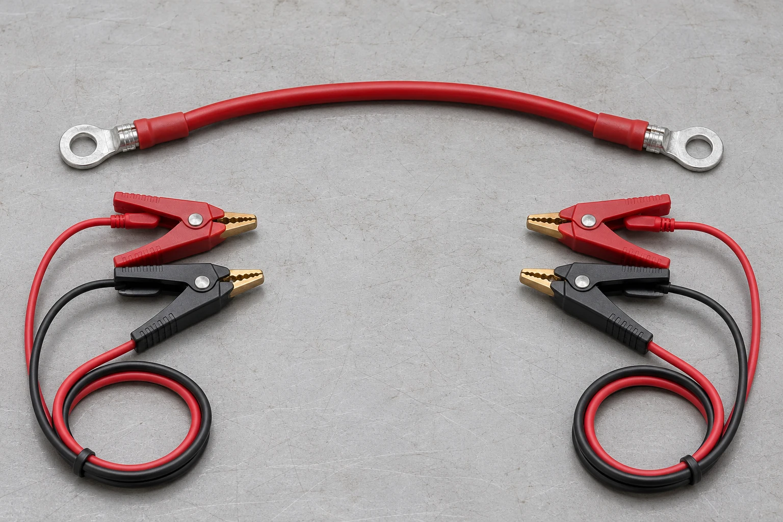
Discuss four-wire measurement when lead and probe effects are significant compared with the resistance you need to resolve.
The method uses separate current and voltage-sensing connections. HIOKI describes this arrangement in its four-terminal measurement explanation.
Position the sensing connections to match the intended boundary. Four wires do not automatically isolate every unwanted interface inside that boundary.
Ask the supplier to confirm instrument capability, fixture design and repeatability for your requirement. A display showing more decimal places does not, by itself, establish adequate accuracy.
For embedded electronics, review allowable test excitation and connection polarity first. Do not apply a generic resistance procedure blindly.
How Should You Resolve A Borderline Result?
A borderline result needs a documented investigation, rather than repeated testing until the assembly passes.
Preserve the first reading and identify the circuit, unit and fixture. Check the applicable drawing revision and test program.
Then review contact seating, fixture condition, instrument status and temperature conditions. Follow the agreed retest procedure before changing or cleaning anything.
Keep fixture maintenance separate from product acceptance. An approved adapter replacement can correct a measurement problem without changing the product limit.
Document the investigation outcome and disposition. Record any approved process change against its effective revision.
What Should Your Supplier Record?
Your inspection agreement should define whether you need pass/fail records, numerical results or both.
| Record | Useful Detail |
|---|---|
| Assembly Identity | Part number, revision and agreed serial or lot identification |
| Circuit Identity | Connector, cavity and defined measurement boundary |
| Test Setup | Program revision, instrument and fixture identification |
| Conditions | Method, settings and required environmental information |
| Acceptance | Limit, units, decision rule and result |
| Exceptions | Retests, investigations and approved disposition |
State the unit explicitly. For example, 0.020 Ω equals 20 mΩ. This is a unit conversion, not a recommended limit.
For broader inspection planning, see the wire harness quality control guide. Resistance results complement other checks rather than replacing them.
What Should Your RFQ Include?
Send the circuit definition and resistance requirement with your drawing, rather than adding testing after the quotation.
Include the BOM, wire specification, lengths, connector references and target quantities. Attach the measurement procedure, limits and reporting requirements when available.
Identify any unresolved requirement as a review item. Ask for agreement before prototype release.
XSD lists DC resistance testing and wire sequence verification among its documented inspection resources. Specific ranges, four-wire configurations and measurement uncertainty require confirmation for your project.
Fixture development, special measurement methods and numerical reporting can affect quotation scope. Compare suppliers against the same inspection package.
A prototype wiring harness can support the agreed review before repeat production. It does not establish an unspecified lifetime guarantee.
Wire Harness Resistance Test FAQ
Use these answers to clarify your purchase specification before release.
Is There One Correct Limit For Every Harness?
No. Define the circuit, application requirement and measurement conditions before selecting an acceptance limit.
Does A Continuity Pass Prove Current Capacity?
No. Current capacity and loaded performance require application-specific evaluation beyond a continuity result.
Can You Compare A Loop Result With One Wire?
Only after accounting for the complete measured path. A loop includes the return conductor and any included interfaces.
Does Four-Wire Testing Remove Every Contact Resistance?
No. Interfaces within the defined sensing boundary remain part of the measurement.
Can You Use The First Sample As The Limit?
No. One sample does not represent all permitted product variation or define your application’s requirement.
Should You Record Ohms Or Milliohms?
Either can work if the specification, instrument output and report use clearly identified, consistent units.
Can The Supplier Simply Raise A Failing Threshold?
No. Changes need engineering review and approval against the functional requirement.
Does XSD Claim A Universal Milliohm Capability?
No. Request confirmation of the range, method, fixture and reporting capability needed for your particular assembly.
Agree The Test Before Approving The Harness
Define the path, method, limit and record format together. Then approve the inspection plan before production. Send your drawing and test requirements for review, including sample quantity and expected annual demand.