
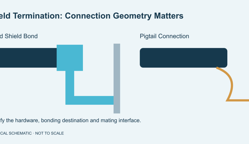
Cable shield termination defines how your cable screen connects to the equipment reference. For high-frequency interference control, a short, broad connection usually outperforms a long pigtail. Specify the termination hardware, bonding destination and inspection criteria before you order.
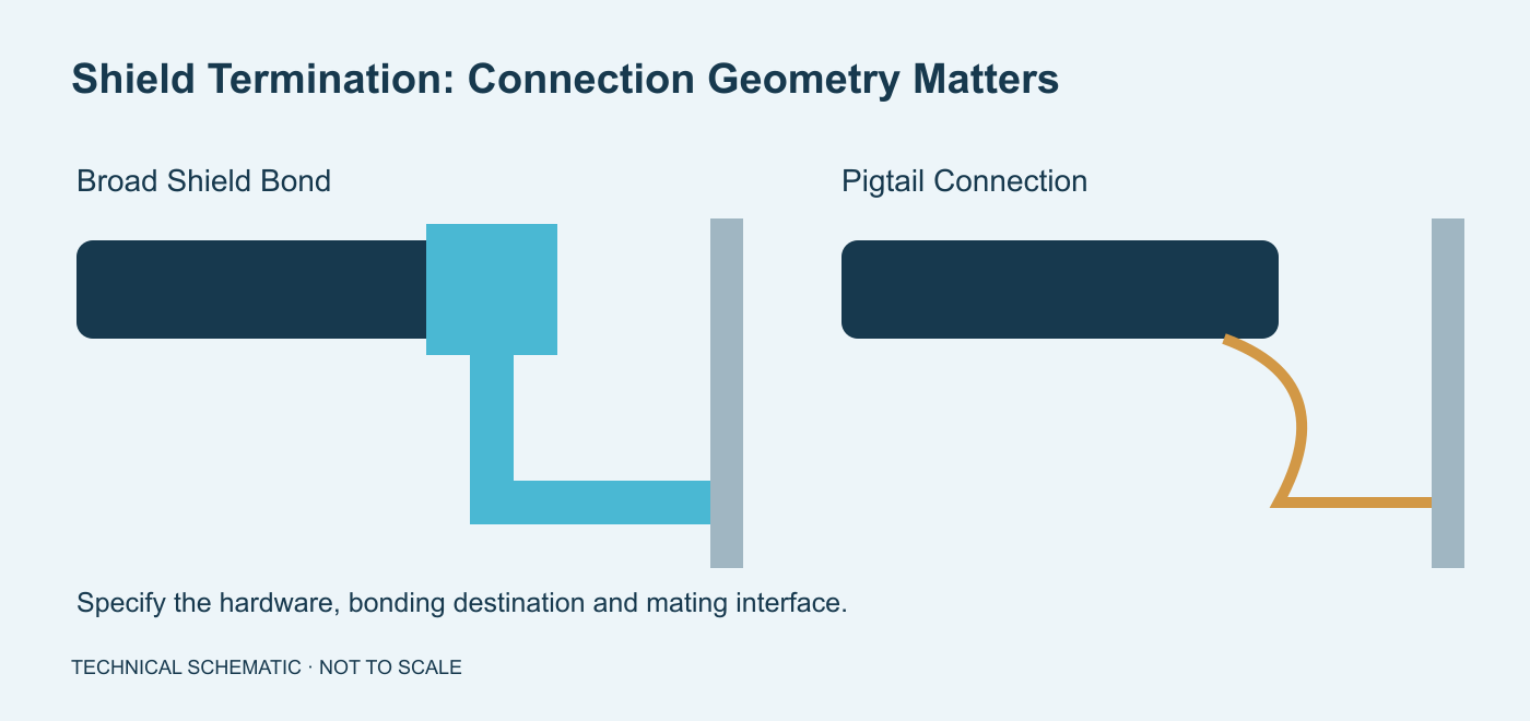
What Changes Between A 360° Bond And A Pigtail?
A 360° bond contacts the shield around its circumference; a pigtail funnels that connection into a narrow lead.
You can implement circumferential contact through a suitable connector, backshell or EMC gland. The hardware must contact the actual shield. Contacting only the plastic jacket cannot provide that connection.
A pigtail uses a drain wire or gathered braid to reach a terminal. Its length and geometry introduce impedance.
DC resistance alone cannot describe this high-frequency behavior. Murata’s shielding guide explains how gathered shield connections impair noise suppression.
| Decision | Circumferential Bond | Pigtail Or Drain Lead |
|---|---|---|
| Geometry | Broad shield-to-hardware contact | Narrow lead to a terminal |
| Drawing detail | Hardware and shield preparation | Lead destination, length and insulation |
| Procurement risk | Incompatible gland or backshell | Unspecified tail or wrong reference |
| Acceptance | Construction and agreed electrical checks | Routing and agreed electrical checks |
When Should You Specify A Broad Shield Connection?
Specify a broad connection when your equipment’s EMC design requires a low-impedance shield bond.
Review this closely around drives, switching equipment and sensitive signal interfaces. Start with the equipment manufacturer’s installation instructions.
Phoenix Contact recommends short shield connections near cabinet entry and explains the disadvantages of twisted braid tails.
The complete bonding path matters. A conductive backshell cannot fix an isolated mounting surface. Check connector shells, enclosure interfaces and bonding hardware together.
When A Pigtail Remains In The Design
Your interface may require a drain lead or a particular single-point connection. Follow the approved circuit and grounding design.
Do not substitute a circumferential bond without engineering approval. Likewise, do not replace specified shield hardware with a convenient lead.
Document unavoidable tail geometry. Its permitted length must come from application requirements, not a universal workshop rule.
Where Should The Shield Connect?
Connect the shield to the reference identified by your equipment design, not whichever terminal is easiest to reach.
Chassis, functional earth, protective earth and signal return have different roles. A shield connection does not automatically replace protective bonding.
One-end versus both-end termination is also a system decision. Interference frequency, potential differences and equipment instructions affect that choice.
SICK’s EMC guide, pages 10–13, explains broad-area connections and cabinet-entry bonding in its industrial context. Do not transfer its recommendations blindly to every analog interface.
What Should Your Shield Termination Drawing Include?
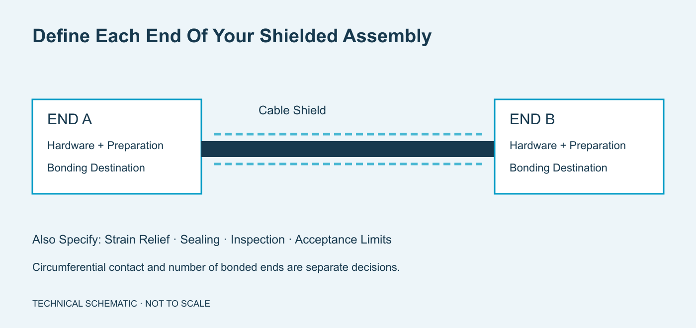
Your drawing should define the shield construction and termination arrangement at both ends.
- Identify cable part number, braid, foil and any drain wire.
- Specify connector, backshell, gland and clamp part numbers.
- Show the bonding destination at each end.
- Dimension jacket removal and exposed shield length.
- Reference the hardware manufacturer’s preparation instructions.
- Define drain lead length, insulation and termination.
- Specify strain relief and sealing separately.
- State inspection methods, limits and sampling.
Do not assume foil and braid use identical preparation methods. Keep shield connections distinct from signal assignments.
Use connector pinout verification to define connector views and circuit mapping.
How Do You Inspect A Shield Termination?
Inspect the physical bond and specified electrical path; neither check alone proves installed EMC performance.
- Confirm cable and shield hardware against the approved BOM.
- Check exposed shield length and preparation before closure.
- Look for damaged braid, loose strands and unintended circuit contact.
- Confirm shield contact, strain relief and mating features.
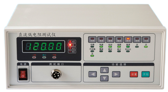
- Measure required paths using agreed test points and limits.
- Check isolation where shield and circuits must remain separate.
Record concealed features before closure when your inspection plan requires evidence.
A continuity beep confirms a conductive path under the tester’s conditions. It does not establish broadband shielding effectiveness.
For reporting, define fixture and measurement boundaries. See wire harness resistance test limits.
Equipment-level EMC validation must address the installed configuration. Agree who performs that validation before approving samples.
What Changes Shield Termination Cost?
Hardware, preparation access and inspection evidence affect cost more than a generic instruction to connect the shield.
A dedicated backshell adds components and assembly operations. Concealed connections may need staged inspection or retained photographs.
Sealing requirements can constrain available glands and cable diameters. Discuss these requirements before choosing substitutes.
Send prototype quantity, production quantity and annual demand. These inputs support tooling and repeatability review without speculative unit prices.
What Can XSD Review For Your Shielded Assembly?
XSD can review your build-to-print cable assembly and its specified termination and inspection requirements.
Published manufacturing capabilities include wire processing, connector assembly and electrical inspection resources.
The quality assurance page documents company certificates and inspection equipment. These do not establish EMC approval for your finished equipment.
Include unusual shield hardware, specialized measurements and reporting needs in the RFQ. Availability and acceptance scope require project review.
Frequently Asked Questions
Resolve the termination geometry and bonding destination before releasing your drawing.
Is A Drain Wire The Same As A Shield?
No. A drain wire provides a connection path for certain shields. It does not replace shield coverage.
Does 360° Mean Both Ends?
No. It describes circumferential contact. Specify which ends connect separately.
Can A Pigtail Pass Continuity But Perform Poorly?
Yes. DC continuity and high-frequency impedance describe different behavior. Installed performance needs appropriate validation.
Can Heat Shrink Replace A Shield Clamp?
Ordinary insulating heat shrink cannot provide a conductive bond. Use the specified shield hardware.
Can You Use A Spare Signal Pin?
Only when the approved interface requires it. A spare pin is not automatically connected to chassis.
Will Any Metal Gland Work?
No. Check actual shield contact, cable diameter, sealing and mounting requirements.
Is One-End Grounding Always Correct?
No. Follow equipment design and installation instructions. Another interface’s rule may create a different problem.
Does A Cable Drawing Guarantee EMC?
No. Equipment EMC also depends on routing, enclosures, references and operating conditions.
Define The Bond Before You Order
Send the cable specification, both end details, bonding destinations and inspection requirements. Include quantities and required records. Contact us for a shielded cable assembly review.