Driver Connection Leads
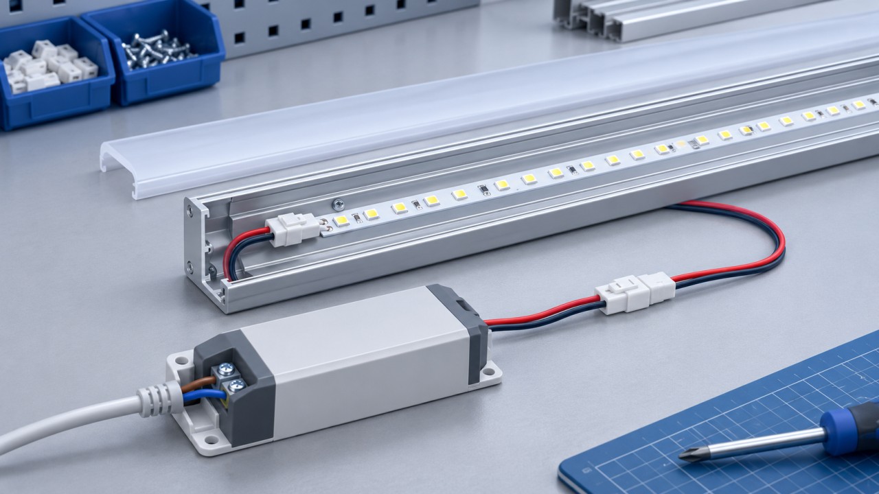
Defined input or output leads, stripped ends or connectorized interfaces.
Specify the driver terminal map, wire construction and strip or termination details.
LIGHTING / OEM INTERCONNECTIONS
Connect the power.
Control the light.
XSD Harness manufactures build-to-print wire harnesses and cable assemblies for lighting equipment. Define each connection—from the power input to the driver, LED module and controls.
WHAT WE BUILD
Lighting wire harnesses connect the electrical parts of a luminaire or lighting system. Their construction depends on the power circuit, driver, light source, controls and installation.
Bring the complete wiring definition to manufacturing: component references, circuit assignments, dimensions, protection and inspection requirements. XSD reviews wire preparation, termination, connector assembly and the selected protective processes against that definition.
FOLLOW THE CIRCUIT
Select a circuit to see what needs to be defined before manufacture.
Input leads connect the specified supply interface to the driver or luminaire. Confirm the actual circuit and equipment class before defining the conductors.
Driver output connections need a clear pinout and a defined electrical load. Confirm whether the selected LED system uses constant-current or constant-voltage operation.
Dimming and sensor circuits follow the selected equipment documentation. DALI, 0/1–10 V and PWM connections have different interface requirements.
Driver architecture: MEAN WELL LED driver guidance ↗
Control interface: DALI Alliance system overview ↗
CONFIGURATIONS TO REVIEW
Defined input or output leads, stripped ends or connectorized interfaces.
Routing between drivers, LED boards and customer-specified components.
Board-to-board or wire-to-module connections with specified mating parts.
Several light modules or channels connected through an approved circuit arrangement.
Connections for the selected dimming, switching or sensing interface.
Cable entries, strain relief and connectorized runs for exposed installations.
APPLICATION CONTEXT
The installation defines the exposure and service requirements. Review these inputs for the actual product.
Downlights, linear luminaires, panels and decorative fixtures.
Review: Internal space, cable entry, service access and heat near the driver or light module.
Equipment lighting and task-lighting assemblies.
Review: Mounting, vibration, maintenance access and the operating environment.
Exposed lighting equipment and external cable connections.
Review: Moisture, UV, temperature, cable sealing and the connector’s mated condition.
Customer-defined lighting circuits for mobile equipment.
Review: Supply conditions, switching, protection, branch routing and vibration.
ENGINEERING INPUTS
Use this checklist to align the design, quotation and sample approval.
| Input | Provide | Confirm during review |
|---|---|---|
| Circuit & load | Schematic, input/output limits, driver and light-module references. | Power, control and earth connections; current in each branch. |
| Wire & insulation | Conductor size, cable reference, insulation and color identification. | Termination compatibility, routing conditions and temperature requirements. |
| Connectors & terminals | Housing, contact, seal and mating-component part numbers. | Circuit assignment, keying, retention and approved sourcing. |
| Geometry & protection | Overall and branch lengths, tolerances, exits, sleeves and strain relief. | Fit, installation access and protection at each exposed point. |
| Control & dimming | Interface, terminal map, routing and any shielding requirements. | Compatibility with the selected equipment and system test plan. |
| Acceptance & supply | Inspection methods/limits, documentation, quantities and required dates. | Sample release, packaging, revision and repeat-order requirements. |
IEC 60598-1 covers general safety requirements and tests for luminaires. Identify the applicable standard, edition and market requirements for your finished product. A component or company certificate does not establish compliance of the complete luminaire.
MANUFACTURE & VERIFY
XSD’s manufacturing processes include wire cutting and stripping, terminal crimping, connector assembly, selected soldering, molding and electrical inspection. The chosen route depends on the assembly.
View manufacturing capabilities ↗
SAMPLE TO PRODUCTION
Check the sample in its real installation before releasing the production revision.
Drawing, BOM, circuit map and unresolved requirements.
Mating, polarity, routing, dimensions and agreed inspection results.
Approved revision, components, labels, packaging and repeat-order criteria.
LIGHTING HARNESS FAQ
A lighting wire harness groups wires, terminals, connectors and protective parts into a defined assembly for a luminaire or lighting system. It may connect the power input, LED driver, light modules, controls or protective earth, depending on the approved design.
XSD can review build-to-print driver leads, internal luminaire wiring, module interconnects and branch assemblies. Send the driver and light-module references, wiring diagram, connector BOM and installation requirements for manufacturing review.
Provide a drawing, BOM, circuit map, wire and connector references, lengths, tolerances and quantities. Include driver input/output requirements, installation temperature, exposure, inspection criteria and required market documentation.
The circuit determines the conductor count. Power, protective earth, dimming, sensors and multiple LED channels can need separate connections. Do not select two-core or three-core wiring from the fixture name alone; use the approved schematic and equipment requirements.
Control leads can be reviewed against the selected driver or controller documentation. Identify whether the circuit uses DALI, 0/1–10 V, PWM or another interface. Define the terminals, polarity where applicable, insulation, routing and any shielding requirements.
Provide load current, circuit voltage, run length, installation temperature and routing conditions. Wire size, terminal compatibility and allowable voltage drop must be assessed together. A wire gauge alone does not establish the rating of the complete harness.
No. Specify exposure at the cable, connector, splice and entry point, including the expected mating condition. A sealed component rating does not automatically apply to the complete assembly. Agree any ingress testing and acceptance criteria for the finished design.
Company quality-system certification is distinct from product approval. Identify the applicable luminaire standard, destination market and required component records. Finished-luminaire compliance must be evaluated for the complete product and its intended use.
Prototype and pilot requirements can be reviewed before repeat production. Use samples to confirm routing, mating, polarity, dimensions and agreed electrical checks. Quantities and timing depend on parts, tooling and the approved manufacturing scope.
YOUR NEXT LIGHTING BUILD
Share your driver, light-module and wiring requirements for a manufacturing review.
XSD Harness is the specialized wire harness and cable assembly business of Dongguan XSD Cable Technology Co., Ltd., Dongguan, China.