

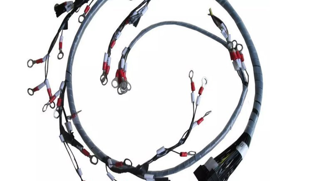
Wire harness length tolerances only work when you define the measurement endpoints and inspection condition. A correct cut length can still produce an assembly that will not fit. Specify finished dimensions, branch locations and installation allowance before you approve samples or compare supplier quotations.
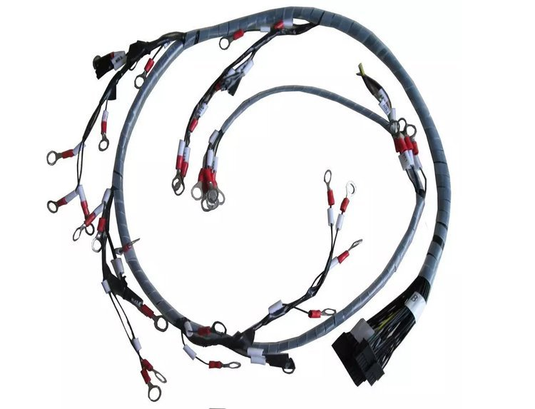
What Does A Wire Harness Length Tolerance Control?
A wire harness length tolerance controls an allowed dimensional range between explicitly identified features under an agreed measurement condition.
You need three separate decisions: the nominal dimension, its permitted variation and the method used to inspect it. Missing any decision leaves room for two reasonable inspectors to disagree.
Start with the function of that dimension. A branch might need to reach a sensor without loading its connector. Another branch might need to remain inside a guarded channel. Those functions can require different limits, even within one harness.
Do not assume that every dimension follows the drawing’s general tolerance block. State which flexible lengths need separate limits. Identify reference dimensions clearly, so purchasing does not mistake installation guidance for a production acceptance requirement.
The recommendations below are a drawing-review workflow, not a replacement for your approved specification. Your component instructions and contractual requirements still govern acceptance.
Separate Cut Length, Finished Length And Installed Reach
Cut length, finished length and installed reach describe different conditions and should not share an unexplained dimension.
Cut length belongs to the wire preparation stage. It describes the material before subsequent operations alter its exposed ends or route. Stripping, termination, insertion and bundling connect that process value to the final assembly geometry.
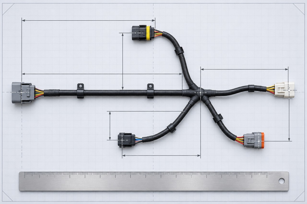
Finished length belongs to the completed assembly. Your endpoints might be connector back faces, terminal features or specified breakout locations. State them beside the dimension rather than relying on an operator’s interpretation.
Installed reach describes whether the assembly fits its actual equipment route. Clips, bends, obstacles and connector approach direction affect that result. A bench measurement cannot reproduce every installation constraint unless your fixture represents those constraints.
You should normally accept the delivered harness against finished requirements. Let the supplier establish appropriate process cut lengths during manufacturing planning. If you also control cut lengths, explain how they relate to finished acceptance.
| Dimension | Question It Answers | Define Before Inspection |
|---|---|---|
| Wire Cut Length | How much material is prepared? | Material state and end preparation |
| Finished Branch Length | Where does this connector end relative to the breakout? | Start feature, end feature and route |
| Installed Reach | Can the connector reach its mate through the approved route? | Clips, bends, slack and mating direction |
Choose Length Datums You Can Locate Repeatedly
Choose physical reference features that both your supplier and receiving inspector can locate without pulling the harness into shape.
A dimension arrow ending somewhere inside a connector outline is ambiguous. It could indicate the mating face, housing rear, cable exit or contact tip. Add a detail view when the relevant feature disappears inside the main drawing.
Molex recommends connector back faces as length references where practical in its Cable Assembly Design Guide. The same guide links tolerance selection to application needs and manufacturing cost.
That recommendation is useful, but it does not settle every assembly. You may need a different feature to represent a mounting interface. Describe your chosen feature precisely and show how the inspector accesses it.
For a ring terminal, identify whether the dimension reaches the hole center or a different defined feature. For a right-angle connector, show the viewing direction and cable exit orientation. Avoid measuring to a floating coupling nut unless its position is explicitly controlled.
Use connector identifiers consistently across the drawing, BOM and inspection sheet. If P1 becomes J1 on another document, resolve that conflict before sampling. A stable feature name makes later engineering changes easier to communicate.
Define The Route And Measurement Condition
Define whether inspectors measure along the harness route or between endpoint positions, and describe its supported condition.
A curved assembly can have a long cable path but a short straight-line distance between its connectors. Those measurements are not interchangeable. Your drawing should identify which one determines acceptance.
Explain how to lay the assembly on the inspection surface. Identify any required locating pins, connector nests or branch supports. Describe whether sleeves and connectors remain free or occupy defined positions.
Do not instruct inspectors simply to pull the assembly straight. Different hand forces can move loose wires and distort flexible branches. If tension is necessary, agree its application method and limit through the inspection plan.
Also define when measurement occurs. A completed, sleeved harness can behave differently from loose terminated wires. Specify any required conditioning when packaging, temperature or material recovery could affect your result.
Keep the method proportionate to the requirement. A simple lead may need only defined endpoints and careful support. A constrained branch assembly may justify a dedicated fixture. Neither approach supplies an automatic accuracy or repeatability guarantee.
Control Branch Locations Without Creating Conflicting Dimensions
Control each functional branch from identified references, and check that your dimension scheme does not impose contradictory limits.
For a multibranch harness, overall length alone cannot describe fit. You also need to locate breakouts, connectors and critical mounting features. A harness can satisfy its overall dimension while placing a sensor branch beyond its allowed route.
Review chained dimensions carefully. If you dimension several segments independently, their allowed variations can accumulate at a distant connector. Do not assume that acceptable individual segments guarantee an acceptable endpoint location.
Conversely, avoid controlling every segment and their total with incompatible limits. Decide which dimensions govern function and which provide reference information. Ask the responsible engineer to resolve the dimension scheme before tooling or inspection planning.
A taped breakout can have a transition region rather than a sharp geometric corner. Define a repeatable reference within that region. You might use a specified sleeve edge or fixture feature, subject to the approved design.
Record connector clocking when orientation affects the installed route. Twisting a branch into position can change its apparent reach and load its termination. A length result without orientation information can hide that installation problem.
Set Tolerances From Fit Requirements, Not Habit
Set length limits from the space your installation needs and the variation your manufacturing and inspection methods can support.
Begin with the shortest usable assembly and the longest manageable assembly. Check connector access, equipment variation and safe routing at both extremes. These boundaries help you choose a meaningful nominal dimension.
You may need unequal upper and lower limits. For example, an installation may tolerate added slack but cannot tolerate a short branch. Another route may restrict excess length because loose cable could approach a moving component.
A Molex Mini-Change customer drawing demonstrates product-specific, length-dependent limits with positive-only allowances. Those values apply to that drawing’s product scope. They are not a default tolerance for your custom harness.
Do not copy a percentage from a catalog without reviewing your assembly. Short branches, rigid terminations and complex breakouts may need different treatment. Ask your supplier to review the proposed limits with the actual construction.
Keep dimensional acceptance separate from electrical and mechanical acceptance. Passing the length inspection does not prove correct pinout, crimp quality or environmental performance. Your inspection plan needs the relevant checks for those characteristics too.
Keep Installation Allowance Separate From Manufacturing Variation
Installation allowance is intentional usable length; manufacturing tolerance is the permitted variation around your specified dimension.
If you need a service loop, include it in the design. Do not expect the supplier’s upper tolerance to supply it. A conforming assembly at the lower limit must still perform the intended installation function.
Review the shortest permitted assembly in its tightest installation condition. Can you connect it without pulling on the connector or violating component instructions? Then review the longest permitted assembly for unsupported loops and interference.
Use the actual mating hardware when practical during prototype fit checks. A connector silhouette cannot show every latch, backshell or approach restriction. Record any difference between the prototype equipment and the released production configuration.
Service access deserves its own review. You may need enough movement to disconnect a module before removing its mounting hardware. Explain that requirement through routing drawings or installation instructions rather than an undocumented preference.
Your broader wire harness design review should connect length, branch layout and mechanical routing. Keep this dimensional decision linked to the equipment, even when different teams own the documents.
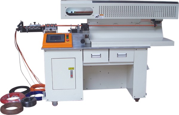
Translate Finished Dimensions Into A Controlled Build
Translate finished dimensions into process settings and assembly instructions, then confirm the relationship through an agreed first-article review.
Your supplier needs the released wire specification, connector references, protection details and dimensional drawing together. A connector substitution can change the relationship between cut length and finished endpoints. Treat such changes as engineering decisions.
Review how the wires enter each connector. Different internal paths can require different prepared lengths within the same connector pair. An equal-length wire set is not automatically the correct manufacturing solution.
After termination, confirm the connector and terminal seating requirements before measuring the assembly. An incompletely seated component can produce a misleading dimension. Correct the assembly condition before interpreting the result.
Then review bundling, sleeves and breakout placement against the approved route. A fixture can help locate features, but its setup must match the drawing. Record fixture identity and revision when they affect acceptance.
Preserve the approved setup information for repeat orders. When a process change affects length, compare finished results before releasing production. Avoid relying on an old machine setting without checking its material and construction context.
Agree A Practical Length Inspection Record
A useful length inspection record identifies the feature, result, method and drawing revision behind each acceptance decision.
Agree the record format before the first shipment. Purchasing needs enough detail to compare quotations and confirm the promised inspection scope. Quality teams need enough detail to repeat the measurement.
Give every controlled dimension a stable identifier. Record its nominal value, allowed range and measured result in the same units. State the measurement condition rather than documenting only a pass mark.
For fixture checks, identify what the fixture actually verifies. A connector reaching a nest may demonstrate a bounded fit condition. It does not necessarily provide a numerical length result for every wire or branch.
Agree sampling and reporting requirements according to product risk and your quality plan. Do not assume every assembly receives a complete numerical dimensional report. Confirm any required full inspection explicitly during the quotation stage.
| Record Field | Why You Need It |
|---|---|
| Part Number And Drawing Revision | Connect the result to released requirements |
| Dimension Identifier And Endpoints | Prevent measuring a different feature |
| Units, Nominal And Allowed Range | Make the acceptance calculation explicit |
| Method, Fixture And Supported Condition | Allow a second inspector to repeat the check |
| Measured Result And Disposition | Separate evidence from the release decision |
| Lot, Sample Identity And Inspection Date | Keep the result traceable to inspected material |
Resolve Supplier And Receiving Measurement Disagreements
Resolve a length disagreement by aligning the measurement method before changing the part or relaxing its limits.
Keep the disputed sample identifiable and preserve its delivered condition. Compare drawing revisions, dimension identifiers and endpoint definitions first. Two teams may have measured different connector features while using the same nominal value.
Next compare the assembly’s support and route. Check whether either team pulled a branch, compressed a sleeve or rotated a connector. Review the instrument and fixture condition when the disagreement remains unexplained.
Repeat measurements using one agreed method and record the observations. If practical, exchange annotated photographs showing the locating features. A photograph helps explain the setup, but it cannot replace the measurement itself.
If repeated results still disagree, involve the responsible quality and design teams. Review measurement uncertainty and the agreed decision rule near a limit. Avoid accepting or rejecting marginal material through informal rounding.
Any concession should identify the affected parts and its authorization. Do not silently alter future production to match an unapproved receiving preference. Update the controlled drawing or inspection instruction when a permanent change is necessary.
Understand What Tight Length Limits Add To Cost
Tighter length limits can add setup, handling, fixture and inspection work, so control the dimensions that affect your installation.
You may need additional first-article measurements or more constrained assembly methods. Complex branches can increase the effort needed to position endpoints consistently. Ask which operations drive the quotation instead of requesting unexplained precision everywhere.
Also distinguish recurring work from development work. A new locating fixture or method study can affect the initial program cost. Inspection and handling may continue with each production batch.
Send expected quantities, annual demand and likely design changes with your RFQ. These details help your supplier assess an appropriate production route. They do not justify a universal unit price or lead-time promise.
When installation freedom allows wider limits, document that decision through engineering approval. Do not loosen a functional dimension merely to reduce price. The useful outcome is a manufacturable assembly that still fits throughout its allowed range.
What Can XSD Review For Your Length Specification?
XSD can review your dimensional requirements alongside its documented wire preparation, connector assembly and harness routing processes.
The XSD manufacturing capabilities page describes cutting, stripping, termination, connector integration and inspection. Those process categories provide context for reviewing your finished assembly requirements.
You should still request confirmation for your particular tolerance, measurement method and reporting scope. This article does not claim a universal dimensional capability. Equipment photographs do not establish measurement uncertainty or a guaranteed result for your assembly.
Supply the drawing revision and identify any installation-critical dimensions. Include the route, connector orientation and protection requirements that affect fit. Ask for unresolved dimensional assumptions to be listed before sample approval.
FAQs About Wire Harness Length Tolerances
Your approved drawing and inspection method should answer length questions before you release the harness for production.
Is There One Standard Tolerance For Every Harness?
No. You need limits appropriate to your construction and installation. A catalog table only applies within its stated scope.
Should You Measure From The Connector Front Or Back?
Use the feature specified on your drawing. Select a repeatable physical reference and identify it in a detail view.
Can You Use Wire Cut Length As Finished Length?
Not without defining the relationship. End preparation, terminations, connector geometry and routing can change what each dimension represents.
Does Overall Length Control Every Branch?
No. Locate installation-critical branches and mounting points separately. Review how their permitted variations affect the complete route.
Should The Inspector Stretch The Harness Straight?
Do not leave that instruction undefined. Specify support and routing conditions, plus controlled tension only when the approved method requires it.
Can A Good Continuity Result Prove Correct Length?
No. Electrical circuit verification and dimensional inspection answer different questions. Include both when your approved inspection plan requires them.
Can A Supplier Suggest Wider Limits?
Yes, but your responsible engineer must evaluate installation consequences. Record any approved change before it governs production acceptance.
What Should You Send For A Length Review?
Send the dimensional drawing, component references, routing information, quantities and inspection expectations. Identify critical endpoints and required reporting explicitly.
Request A Drawing-Based Harness Review
Send one controlled drawing package so XSD can review your length requirements with the complete assembly configuration.
Contact us with your drawing and BOM, connector references, installation route, target quantity and annual demand. Include required dimensional reports and sample approval criteria.
Define the endpoints, inspection condition and allowed variation before approving a harness. That gives both teams a repeatable acceptance method. Confirm installation fit separately, using the shortest and longest permitted configurations where practical.
