Moisture & Water
Condensation, rain, splash and washdown need different design inputs. Define exposure, installation position and mating condition. Review sealed connectors, heat shrink, tubing and molded transitions.
MARINE / BOAT EQUIPMENT / OEM
Defined for the connection.
Prepared for the environment.
XSD Harness manufactures build-to-print wiring harnesses and cable assemblies for boat systems, marine electrical equipment and related OEM applications. Your drawings, BOMs, connector specifications, routing and environmental requirements define the build.
THE MANUFACTURING BRIEF
Your installation conditions determine the marine harness specification.
From an enclosed instrument panel to a splash-exposed deck connection, each location creates different requirements. XSD reviews the electrical interfaces, materials, branch layout and protective processing around your approved equipment design.
Send the required standards and acceptance criteria with your RFQ. We review component availability, tooling, manufacturing operations and inspection scope before committing to the build. Discuss application-specific assemblies
EXPOSURE → DESIGN INPUT
Start with the exposure at each connection. “Marine” alone does not define a sealing or material requirement.
Condensation, rain, splash and washdown need different design inputs. Define exposure, installation position and mating condition. Review sealed connectors, heat shrink, tubing and molded transitions.
Define salt-containing exposure at contacts, terminals and conductive interfaces. Select material, plating, connector sealing and protection against the approved operating environment.
Engines, pumps, motors and deck equipment can load the wiring. Review strain relief, connector retention, support points, clips and any repeated cable movement.
Identify edges, penetrations and moving parts along the route. Specify conduit, sleeving, tape, heat shrink, clips or molded transitions where needed.
State operating temperatures and relevant humidity, sunlight, oil, fuel or chemical exposure. Material selection remains specific to the location and approved component requirements.
FROM POWER TO SIGNAL
Customer-defined circuits connect the vessel equipment to the approved electrical architecture.
Connections for customer-defined engine sensors, control circuits, alternators, starters and monitoring equipment. Confirm heat, vibration, connector access and service requirements.
Cable assemblies for GPS, radar interfaces, gauges, displays and monitoring equipment. Specify the interface, shielding, pinout and any signal-validation requirements.
Connections for battery banks, switches, inverters, chargers and distribution equipment. Define circuit current, voltage drop, terminals and protective devices in the system design.
Harnesses for pumps, float switches, alarms and auxiliary equipment. Identify splash or immersion exposure at each installed connection.
Cabin, deck, navigation and equipment-lighting circuits. Specify loads, connector interfaces, branch lengths and the exposure of each lamp connection.
Switch panels, controls and monitoring panels with defined cavity assignments, wire IDs, grounding and mating interfaces.
Winch, actuator, motor and auxiliary-equipment connections. Review cable support, movement, abrasion points and installation access.
Temperature, pressure, level, position and equipment-monitoring circuits. Match the specified connector, cable and signal requirements.


VESSEL / EQUIPMENT SCOPE
Harness requirements are reviewed for the actual equipment, location and electrical interface.
| Application | Harness Focus | Key Input |
|---|---|---|
| Recreational Boats | Lighting, controls, batteries and electronics | Circuit loads and installation exposure |
| Yachts | Navigation, cabin, panel and equipment wiring | Routing, service access and interfaces |
| Work Boats | Engine, control, sensor and auxiliary circuits | Operating conditions and protective requirements |
| Marine Equipment | Pumps, motors, sensors and controls | Equipment specification and mating parts |
| Boat Trailers | Specified lighting and auxiliary connections | Connector interface and road / water exposure |
| Marine Electronics | Display, signal, sensor and control assemblies | Pinout, shielding and signal acceptance |
INDUSTRY → ASSEMBLY
Choose the assembly route around your approved interfaces, protection requirements and installation.
Sealed interfaces, controlled wire entries and protected branch transitions, subject to the approved sealing design.
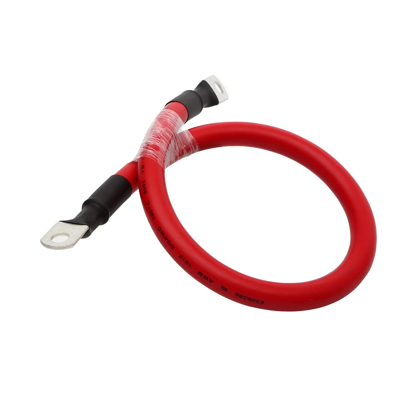
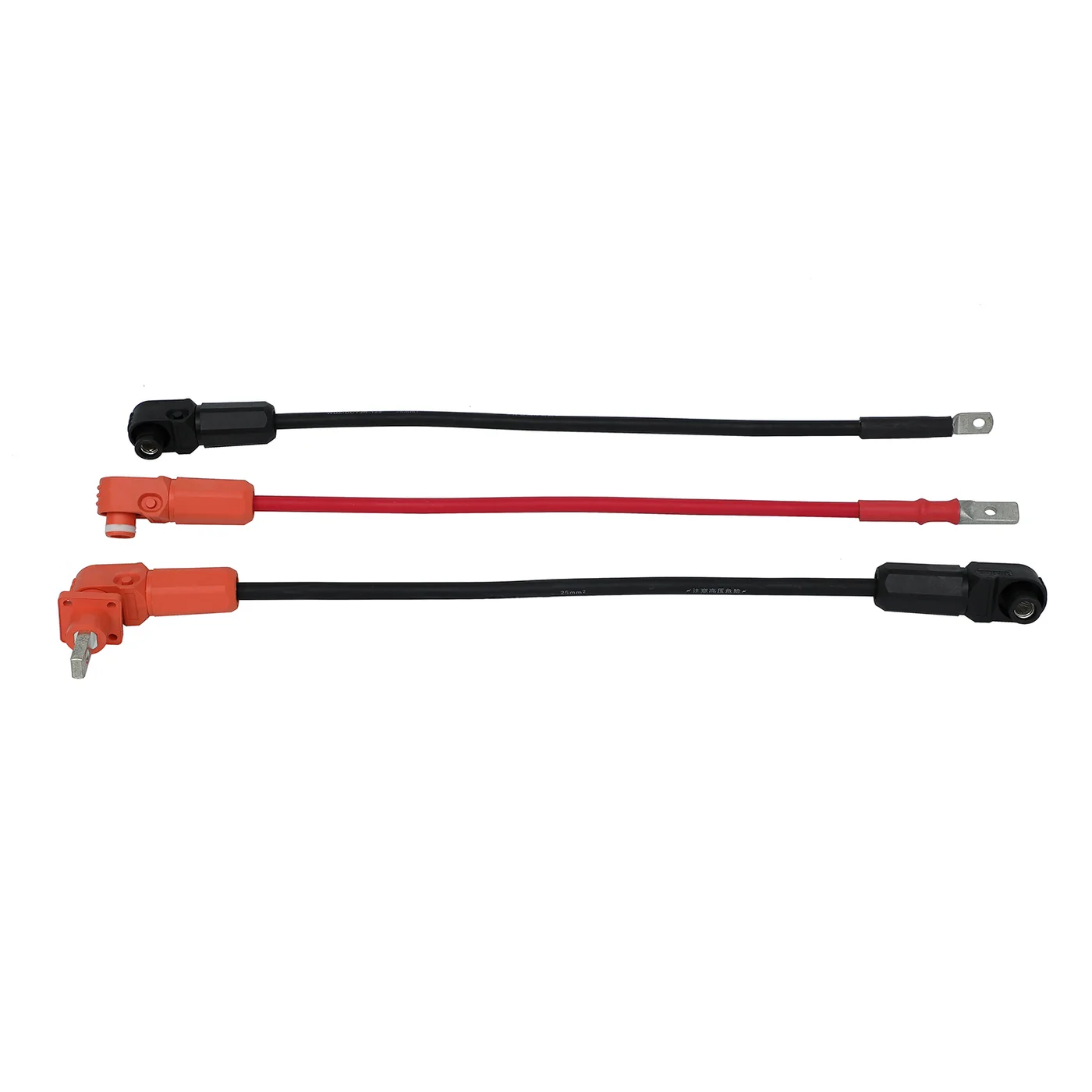
Specified conductor sizes, polarity, ring terminals, insulation and cable lengths for the approved power layout.
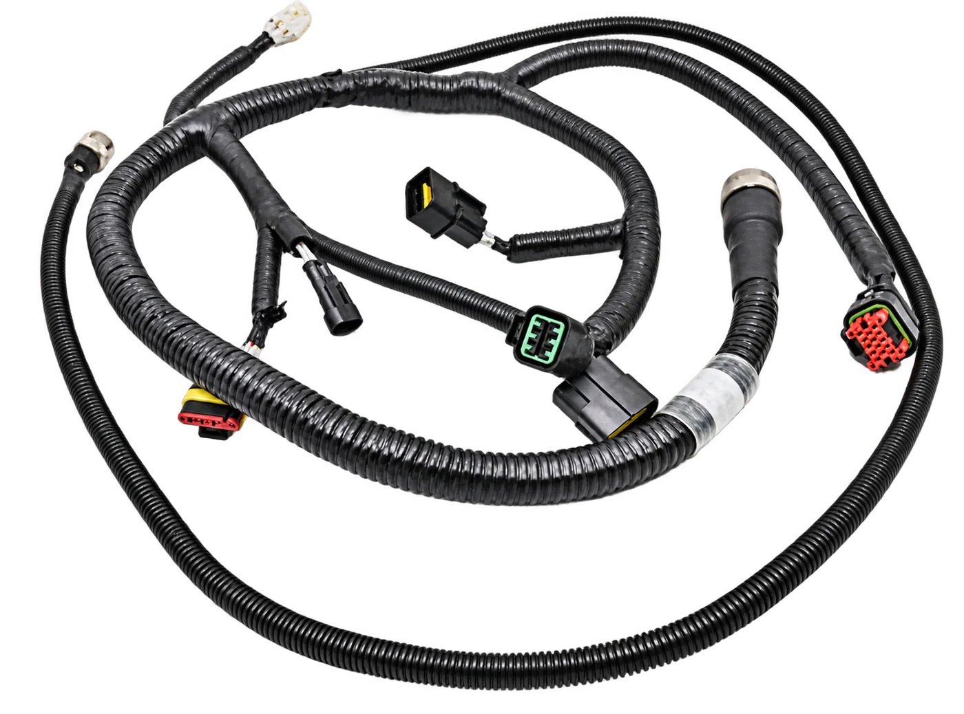
Multi-branch connections for approved engine-related circuits, with identification and installation-specific protection.
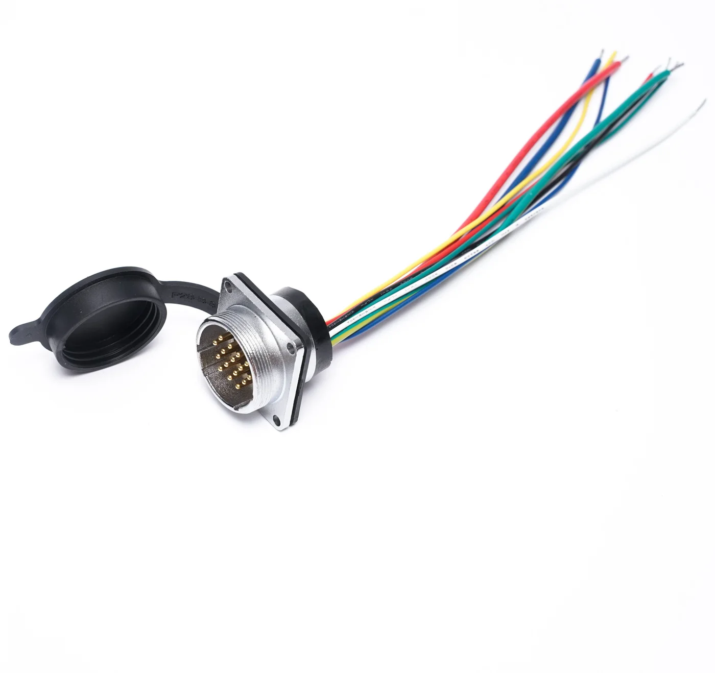
Customer-defined panel interfaces, circuit assignments and branch dimensions for equipment integration.
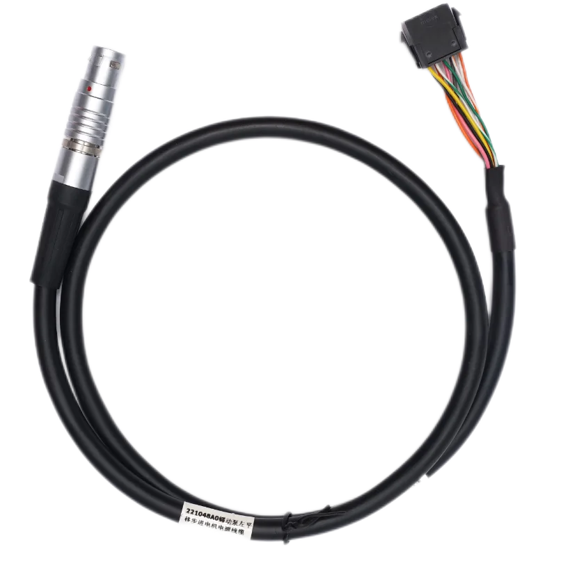
Sensor and monitoring connections manufactured to the specified component references and pinout.
Molded cable entries and connector transitions reviewed for material compatibility, geometry and protective function.
YOUR DRAWING IS THE STARTING POINT
XSD manufactures OEM configurations from customer-approved drawings, BOMs, wiring diagrams and specifications.
ELECTRICAL CONFIGURATION
MECHANICAL / ENVIRONMENTAL
Specify dimensional tolerances and permitted component alternatives. These inputs control the quotation, prototype and repeat build.
COMPONENTS BEFORE CLAIMS
Select each component for its approved electrical, mechanical and environmental duty.
THE COMPLETE SEALING PATH
Waterproof performance depends on the complete harness design and its validation method.
A sealed connector or molded section alone does not make an entire harness IP67 or IP68. Define the finished assembly, installation condition and required test. Explore waterproof wiring harnesses
MATERIALS / PLATING / VALIDATION
Salt-containing moisture can affect exposed conductive interfaces. Define the protection and acceptance requirements before manufacture.
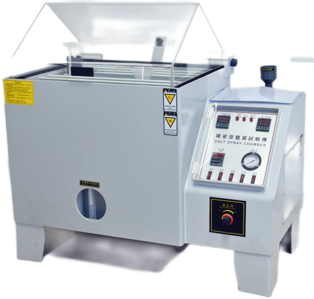
XSD has a precision salt spray tester among its inspection resources. Agree the sample configuration, method, duration, assessment points and acceptance criteria for your project.
A salt-spray result is not a direct prediction of years at sea. ASTM B117 cautions against using standalone results to predict natural-environment performance.
Method · Sample condition · Exposure duration · Assessment · Acceptance
SUPPORT THE ROUTE
Harness routing and fixing points should limit unsupported loads and repeated bending at electrical terminations.
DRAWING → CONTROLLED BUILD
The manufacturing route follows your approved design, components and inspection requirements.
Drawings, BOM, wiring diagram, equipment and environment.
Wire, connectors, terminals, seals, sourcing and tooling.
Cutting and stripping to approved dimensions.
Specified crimping, insertion and component checks.
Branches, sleeves, conduit, clips and identification.
Protective processing where the approved design requires it.
Specified electrical, dimensional, mechanical and environmental checks.
Approved prototypes, pilot builds and repeat production.

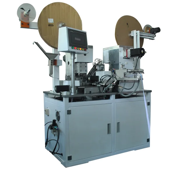

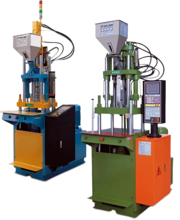
Individual operations apply only where required by the approved assembly. View manufacturing capabilities
AGREE THE EVIDENCE
Testing is selected according to the approved product specification and environmental requirements.
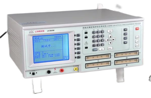
Continuity, wire sequence and DC resistance against defined criteria. Withstand-voltage requirements need method and capability confirmation.

Crimp inspection, terminal cross-section analysis and pull-force testing where specified. Match checks to the approved terminal and wire.

Dimensions, connector mating / unmating and bending tests where applicable. Define setup, loading, cycles and acceptance limits.
Salt-spray testing for selected components or assemblies. Other environmental checks require an agreed validation route and responsibility.
Not every marine harness requires every listed test. Equipment availability does not establish a universal limit, certification or service-life guarantee.
IP requirements refer to a defined protection assessment. Review sealing and validation or consult the IEC 60529 scope ↗.
DEVELOPMENT TO REPEAT BUILDS
Use the prototype to resolve fit, function and environmental requirements before releasing the repeat-build configuration.
Record the approved components, pinout, branch dimensions, protection and inspection plan. Confirm any design changes before the next build stage.
Quote sample quantities separately from annual demand. Component lead times, tooling, approval work and validation scope influence the supply plan. Prototype wiring harnesses
MANUFACTURING BASIS
XSD combines build-to-print assembly with a wider wire and cable manufacturing background.
Drawings, BOMs, wiring diagrams and samples support a defined manufacturing review.
Dongguan XSD Cable Technology Co., Ltd. supports the dedicated XSD Harness business.
Vertical and low-pressure molding resources support selected protective processes.
Customer-approved parts define connections, sourcing and the assembly method.
Electrical, tensile, bending and salt-spray resources support project-specific checks.
Development, pilot and repeat builds follow an approved configuration.
Company quality systems are distinct from marine-specific product approval. Applicable standards and documentation are reviewed for each project.
PREPARE YOUR RFQ
Provide the available information and identify open items. Clear inputs help define the build scope and quotation.
ENGINEERING & PROCUREMENT
These answers define the inputs needed for a project-specific marine harness review.
Send the vessel or equipment application, drawing, wiring diagram, BOM, wire and connector specifications, branch dimensions and quantities. Include water and salt exposure, temperature, vibration, sealing requirements and inspection criteria. Identify unresolved items for review.
XSD can review sealed connectors, cable seals, heat shrink, molded entries and protective components for the approved design. Waterproof or IP performance depends on the complete assembly and validation method. A component rating alone does not establish a finished harness rating.
Customer-specified sealed or environmental connector systems can be reviewed, subject to component identification, sourcing availability, tooling and assembly compatibility. Provide the housing, contact, seal, cavity-plug and mating connector references.
XSD has documented salt-spray testing resources. The sample configuration, method, duration, inspection points and acceptance criteria must be agreed for each project. Salt-spray results do not establish a universal service life.
Yes, battery and power connections can be reviewed where defined by the approved project. Specify operating voltage, circuit current, conductor construction, terminal interfaces, polarity, insulation and routing. The vessel electrical design defines protection and system requirements.
A physical sample can support the review. Component identification, dimensions, circuit assignments, materials and inspection requirements still need customer approval. Record the approved drawing and BOM before repeat production.
Prototype and first-article builds can be reviewed before pilot or repeat production. Agree component availability, tooling, sample quantity, timing and inspection scope. Fit, function and environmental acceptance requirements should be defined before release.
Selection depends on conductor construction, terminal material and plating, jacket properties, connector sealing and actual exposure. Specify the applicable material and component requirements. No single jacket, coating or connector makes every marine assembly suitable for every location.
YOUR NEXT MARINE BUILD
Send your drawing, BOM, wiring diagram and environmental requirements. XSD can review the components, manufacturing route and inspection scope for your assembly.
Discuss Environmental Requirements ↗
XSD Harness is the specialized wire harness and cable assembly business of Dongguan XSD Cable Technology Co., Ltd., based in Dongguan, China.