
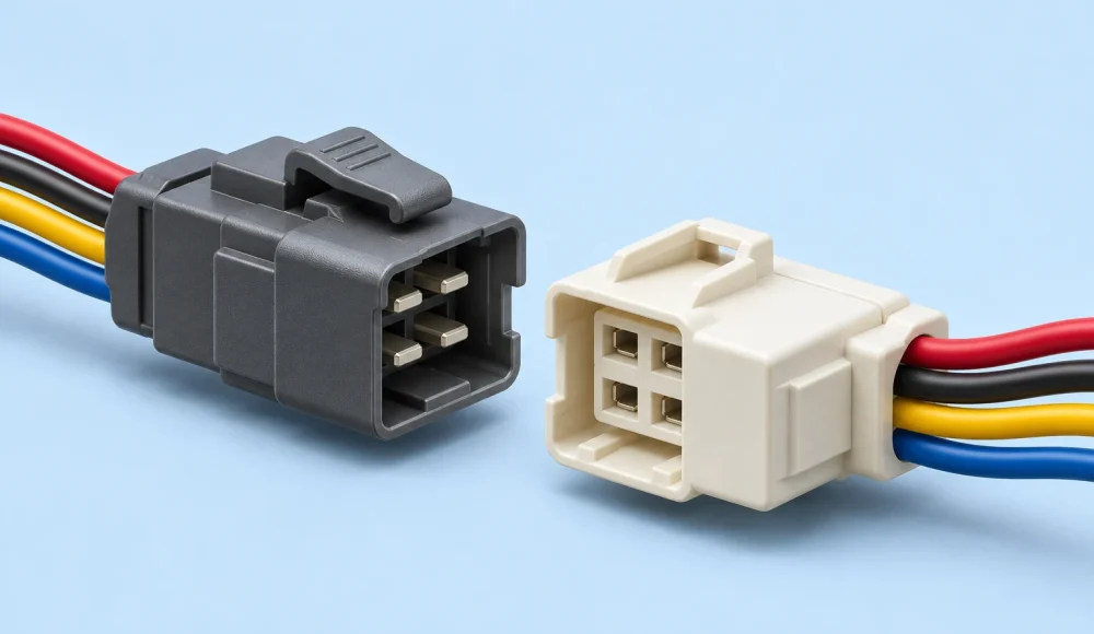
Connector mating cycles describe repeated connection and disconnection under defined conditions. You need a requirement that includes production testing, installation and servicing. Match that requirement to the exact connector pair, contact finish and application. A cycle rating alone does not guarantee your harness will survive its operating environment.

What A Connector Mating Cycle Actually Covers
A mating cycle normally includes one complete mating and one complete unmating of the specified connector pair.
Check the manufacturer's definition before comparing products. Your internal counting convention must match the qualification document. Record any partial insertion separately when it could damage contacts or locking features.
The rating belongs to a defined configuration and test sequence. It does not describe every connector sharing a similar housing. Contact geometry, finish, counterpart and handling can change the result.
You also need the acceptance criteria after cycling. A connector that still fits together may have unacceptable electrical resistance or damaged locking features. Mechanical movement alone cannot demonstrate electrical suitability.
Separate connector durability from calendar life. A connection may remain mated for years yet experience few deliberate operations. Another connection may be handled repeatedly within one production shift.
Those applications need different evidence. Your first question should identify how the connection is used, rather than request the largest catalog number.
Build A Mating Cycle Budget Before Selecting Parts
Your cycle budget should include every planned connection and disconnection affecting each physical connector half.
Start with the product route from harness manufacture to final installation. Include electrical testing, troubleshooting, integration checks and installation retries. Then add planned maintenance and expected module replacement.
Count operations for individual interfaces. A connector at the controller may stay untouched when you replace a sensor branch. Assigning identical service counts throughout the harness can conceal the interface that receives the most handling.
For a hypothetical module, consider four production cycles, two integration cycles and twelve planned service cycles. That creates eighteen planned cycles. These figures illustrate counting only; they are not recommended requirements or product ratings.
Your engineering team must then address uncertainty. Define allowance for commissioning retries, diagnosis and unplanned repairs. Do not apply an unexplained universal multiplier and call the design qualified.
Document who owns each estimate. Production understands test access, while service teams understand field replacement. Purchasing should receive the agreed requirement rather than reconstruct it from disconnected emails.
| Stage | What To Count | Decision To Record |
|---|---|---|
| Harness Production | Each test connection and approved retest | Connector handling route |
| Equipment Integration | Commissioning and assembly checks | Installation sequence |
| Scheduled Service | Each planned module disconnection | Maintenance schedule |
| Troubleshooting | Reasonable diagnostic allowance | Engineering assumption |
| Test Fixture | Every unit tested through the same counterpart | Replacement policy |
A fixture counterpart has its own budget. It may see hundreds of products while each shipped harness sees only one fixture. Keep these histories separate when reviewing failures.
Read The Durability Specification Beyond The Cycle Number
A useful connector durability specification states the configuration, cycling method and performance required after cycling.
Identify the complete part numbers for both halves. Include terminals, contact finish and any relevant locking components. Check the applicable document revision against the purchasing specification.
Look for the test method, cycling rate and sample preparation. Determine whether the sequence includes environmental conditioning. A mechanical durability result cannot automatically establish performance after contamination, vibration or temperature exposure.
The Molex Ultra-Fit specification illustrates why details matter. Its durability section distinguishes tin and gold configurations, with different cycle counts. It also defines cycling conditions and post-test electrical and visual criteria.
Use that document as an example of specification structure. Do not transfer its values to another connector family or unspecified terminal combination. Confirm the exact applicable configuration with the component manufacturer.
Also distinguish initial resistance from permitted resistance change. A change limit compares measurements against a baseline. It is not automatically the allowable resistance of your complete finished harness.
Your harness resistance test limits should identify measurement boundaries and fixture contributions. Otherwise, test lead variation can obscure the connector behavior you intended to assess.
Match Contact Finish And Counterpart As A System
Select contact finish using the approved connector combination and application conditions, rather than color or a generic durability claim.
Review both sides of the interface. A harness terminal specification is incomplete when the equipment header remains undefined. Similar dimensions do not establish an approved mating combination.
Request the finish designation and applicable drawing. A purchasing description such as “gold connector” may omit the contact area, thickness option or exact terminal reference. These omissions make comparison unreliable.
Avoid assuming that one finish always solves a high-cycle requirement. The manufacturer's evidence applies to its specified contact system. Your environment, handling and electrical application still require review.
Assess alternatives using the same criteria. Compare the approved pair, documented durability, locking arrangement, service access and availability. A lower component price may require a different maintenance strategy.
Confirm substitution controls before ordering. A supplier must not replace terminals solely because the housing accepts them. Any alternative needs technical approval covering the mating interface and required performance.
Keep the approved references in the bill of materials. Link them to your harness revision controls so a purchasing change triggers an engineering review.
Make The Connector Accessible In The Equipment
Service access should let you release the specified lock and separate the housings without loading the wires.
Review the connection in the actual enclosure. A connector can work perfectly on a bench yet become difficult to release behind another module. Check the installed arrangement before approving harness lengths.
Allow space for the required hand or manufacturer-approved tool. Consider gloves, neighboring components and the removal path. Do not assume the assembly opening provides enough access after every component is installed.
Provide a controlled service loop where the design needs one. It should support access without introducing sharp bends, abrasion or interference. Determine its length from the installed geometry and cable requirements.
Separate cable support from connector handling. A nearby support should manage routing loads while preserving the movement needed for correct release. Its position must not force the wires sideways at the housing.
Review the latch instructions for the selected family. The Molex Milli-Grid application specification describes alignment and latch release for its defined connector system. Other interfaces may require different actions or tools.
Use a representative enclosure sample for this review. Photographs can document clearance, but they cannot replace checking the complete service movement. Record any required routing changes before production release.

Distinguish Latches, Secondary Locks And Terminal Retention
Connector locks and terminal retention features control different interfaces, so you should inspect and operate them separately.
A housing latch keeps the connector halves together. Terminal retention keeps individual contacts seated inside a housing. A connector may appear latched while a contact remains incorrectly positioned.
Some families add connector position assurance, commonly called CPA. Others use terminal position assurance, or TPA. The Molex retention guide explains these separate functions. Verify the installation and release sequence for your actual components.
Do not force a secondary lock through resistance. Stop and inspect the assembly according to the component instructions. A mispositioned contact, incorrect part or damaged feature may require correction.
Likewise, an audible click is useful feedback but not a complete inspection method. Define the visual or dimensional checks that confirm full engagement. Include any secondary lock position required by the application specification.
Keep durability inspection separate from destructive retention testing. Repeatedly pulling on wires to prove connector engagement can create another failure mechanism. Use the approved inspection method and any specified verification load.
For procurement, request clear acceptance records for both interfaces. You can also review the difference between crimp pull force and terminal retention. Neither result alone establishes repeated mating performance.
Control Wear At Production Test Interfaces
A production test counterpart needs a documented inspection and replacement policy because it accumulates cycles across many assemblies.
Identify each fixture and replaceable adapter. Record the counterpart part number, installation date and accumulated operations. Capture retests as well as initial tests when they use the same interface.
Choose the counting method that fits the process. An electronic counter can help where the fixture supports it. A controlled log may suit a lower-volume route. The method must follow actual operations consistently.
Inspect the counterpart for damage, contamination and abnormal engagement. Define the response when mating force changes or electrical readings become unstable. A suspect fixture should not continue rejecting production without investigation.
Consider a replaceable adapter where repeated access justifies it. The adapter must preserve the required circuit mapping and measurement performance. Its additional interfaces become part of the test setup and need control.
Do not claim an adapter removes all fixture error. It can introduce resistance, alignment issues or another wear point. Verify the complete measurement path after replacement using the approved method.
When defects cluster around one station, compare fixture histories before concluding that every harness is defective. Retain suspect parts and distinguish assembly faults from counterpart damage.

Agree A Durability Validation Plan
Your validation plan should connect the required cycles to defined samples, operating conditions and measurable acceptance criteria.
Begin with the approved connector pair and representative harness construction. Include relevant mounting, cable support and release access. A loose component test may not reveal problems caused by the installed routing.
Specify the sequence before testing. State when you measure electrical performance, inspect locks and evaluate mating behavior. Identify which checks occur initially, during cycling and after completion.
Define the electrical state explicitly. Do not assume mechanical mating durability authorizes connection or disconnection under load. Use the component documentation and equipment safety requirements to determine permitted operation.
If your application requires environmental conditioning, agree its relationship to cycling. Different sequences answer different questions. A dry bench test cannot establish behavior with field dirt or moisture present.
State the sample quantity and responsibility in the purchase documentation. Your product requirements, risk assessment and applicable component instructions should drive that decision. There is no universal sample count for every harness program.
Record failures rather than only the final result. Note the cycle history, observed damage, measurement conditions and affected interface. This evidence helps distinguish handling, component selection and assembly causes.
Finally, agree the disposition of tested samples. A heavily cycled validation sample should not silently enter the normal shipment stream. Keep its status visible in the inspection records.
Compare Durability Cost At The Interface Level
The practical cost of connector durability includes components, assembly, validation and the effort required to service the equipment.
Compare complete solutions against the same service requirement. A higher-cycle interface may reduce planned replacement work. A simpler connector may suit an internal connection that rarely opens.
Include access costs in the comparison. If technicians must remove several modules to release one latch, connector price becomes a small consideration. A routing or placement change may create more value.
Review tooling and assembly changes for each alternative. A new terminal may require different approved crimp tooling and validation. Do not evaluate the housing alone while ignoring the termination process.
Consider supply continuity without approving uncontrolled substitutes. Record acceptable alternatives and their supporting evidence before a shortage occurs. The connector pair must remain technically defined throughout purchasing.
For fixture interfaces, compare planned adapter replacement with unplanned troubleshooting and false rejects. Use your actual production data. Avoid assigning invented savings to a change before the process has been evaluated.
Your final comparison should show both the purchase decision and its assumptions. When service frequency changes, revisit the decision rather than relying on an outdated cycle estimate.
Review Your Mating Requirements With XSD
You can ask XSD to review a custom harness against your defined connector references, routing and inspection requirements.
XSD's manufacturing capabilities describe connector assembly, crimping and electrical inspection within its build-to-print workflow. These capabilities support discussion of your harness construction. They do not establish an unlimited mating life for every connector.
Send both mating part numbers and the equipment interface information. Include your cycle budget, service access constraints and required acceptance records. Identify any connector that production testing will handle repeatedly.
Separate routine production checks from additional durability qualification. Agree the test method, sample plan, responsibility and quotation scope before ordering. Do not assume a continuity check includes an endurance program.
Where information is incomplete, mark it for engineering resolution. An approved sample can confirm fit and handling. It does not replace the documented service requirement or relevant qualification evidence.
Frequently Asked Questions
You should resolve cycle definitions, test conditions and service handling before approving a connector for repeated use.
Does A Cycle Rating Guarantee Field Life?
No. It describes performance under the documented qualification conditions. Your environment, counterpart, routing and handling must also be suitable. Confirm the required evidence for the installed application instead of treating a cycle number as a warranty.
Should Production Tests Count Towards Mating Cycles?
Yes, include them in the connector's handling history. Count the harness interface separately from the fixture counterpart. The fixture usually accumulates operations across multiple products, while each harness follows its own route.
Can You Reuse A Connector After Its Rated Cycles?
Do not assume continued suitability merely because it still connects. Follow the manufacturer's guidance and your approved maintenance policy. Additional use needs an engineering decision supported by the application requirements and relevant evidence.
Is A Higher Cycle Rating Always Better?
Only when the complete connector system meets your other requirements. Consider electrical performance, environment, size, locking, service access and cost. A large cycle number cannot compensate for an unsuitable mating pair or inaccessible release mechanism.
Can A Strong Latch Prove Contact Durability?
No. The latch and electrical contacts perform different functions. Confirm mechanical engagement and electrical acceptance separately. Your inspection plan should also address terminal seating and any required secondary locks.
Send Your Connector Service Requirements
Send your drawing, mating references, cycle budget and expected quantities for a focused review. Include test and service access requirements. Contact XSD for a harness quotation so the proposed construction and inspection scope match your intended use.