Center conductor
Carries the electrical signal.
OEM / BUILD-TO-PRINT INTERCONNECTS
Specified from the inside out.
XSD Harness manufactures custom coaxial cable assemblies according to customer drawings, BOMs, cable specifications, connector part numbers and dimensional requirements. Our production capabilities support cable preparation, selected crimping and soldering processes, connector integration, protective processing and project-specific inspection.

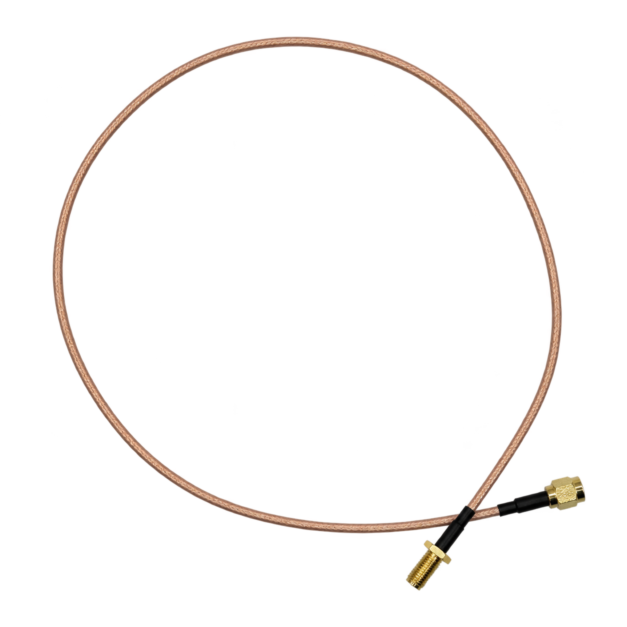
FINISHED SIGNAL INTERCONNECTS
A coax cable assembly combines a coaxial cable with one or more specified connectors or terminals to create a finished signal interconnect. Its construction typically includes a center conductor, dielectric insulation, shielding and an outer jacket, helping control the electrical path and reduce external interference.
XSD manufactures coax assemblies according to customer-defined cable type, connector, length, routing, protection and inspection requirements.
This page focuses on physical construction and the finished assembly. For high-frequency application requirements, see RF Cable Assemblies →
FOUR LAYERS. ONE COAXIAL STRUCTURE.

Construction illustration — not a product specification. Materials and dimensions follow the selected cable.
Carries the electrical signal along the center of the coaxial structure.
Carries the electrical signal.
Separates conductor and shield, and influences electrical characteristics.
Helps reduce electromagnetic interference and provides the outer electrical reference.
Provides mechanical and environmental protection.
SELECT THE ASSEMBLY FORMAT
These formats are reviewed against your selected components and process requirements. A configuration name does not establish electrical performance or connector availability.
Point-to-point assemblies using customer-defined cable and connector combinations.
Compact electronic interconnects for space-constrained applications, subject to connector and process review.
Small-format solutions for embedded electronics where routing space and component compatibility matter.
Molded strain relief or connector protection where compatible with the approved design.
Different connector interfaces at each end according to the approved BOM.
Multiple separate coaxial lines grouped to organize routing and cable management.
BEGIN WITH THE CABLE DATASHEET
Cable choice sets the starting point for dimensions, routing and termination. Supply the manufacturer reference instead of choosing by jacket color or appearance.
For general routed assemblies within the specified bend and installation limits.
Compact and lightweight electronic assemblies.
Dense electronic interconnections, subject to process compatibility.
Selected for project electrical and environmental requirements.
Customer-nominated part numbers where sourcing and process compatibility are confirmed.
MATCH BOTH ENDS
XSD can manufacture coaxial assemblies using customer-specified connector part numbers, subject to sourcing availability and process review.
Manufacturer, part number, mating interface, contact and cable compatibility.
Matching or different connector, direction, mounting and termination requirements.
Confirm the connector-to-cable combination, not just the family name. Contact, ferrule and cable dimensions must suit the selected termination. Connector families are confirmed per project rather than presented as an unverified inventory.
DEFINE THE CONNECTION, THEN THE PART NUMBERS
The specified connector system at both ends of a point-to-point cable.
Different approved connector interfaces connected by the specified coax.
Small-format contacts and housings, subject to cable and tooling review.
A defined board-level mating interface for compact equipment.
One connector and an open end prepared to the approved termination dimensions.
Connector direction and relative orientation specified for the installation.
Additional transition protection or strain relief where compatible with the design.
Separate coaxial lines organized into a routed harness; not an implied signal splitter.
TURN “CUSTOM” INTO A BUILD SPECIFICATION
Cable.
Connector.
Length.
Built together.
| Parameter | Customizable item |
|---|---|
| Cable | Customer-specified coax type and cable part number |
| Connector | Specified connector family and exact part number |
| Length | Custom overall length and dimensional tolerance |
| Connector direction | Straight / right-angle where supported; defined orientation |
| Shielding | According to cable construction and termination requirements |
| Termination | Crimp, solder or the specified approved method |
| Protection | Heat shrink, sleeve, tube or molding |
| Labeling | Customer part number, revision or identification |
| Branching | Cable routing and breakouts where required by the assembly design |
| Packaging | Project-specific packing and handling requirements |
GENERAL MANUFACTURING WORKFLOW
The route is selected for each approved assembly, not imposed as a fixed process for every cable.
Review cable specification, connector part numbers, dimensions, application, quantities and inspection requirements.
Cut and prepare cable to specified dimensions.
Shield and jacket preparation methods are reviewed according to the selected coax cable and connector system.
Crimp, solder or otherwise terminate the connector using the approved method.
Apply heat shrink, sleeves, molded strain relief or identification where required.
Perform project-defined electrical, dimensional and mechanical checks.
Jacket, dielectric and shield dimensions are reviewed against the connector requirements. Specialized automated braid preparation is not presented as a confirmed in-house process without equipment and process evidence.
CONTACTS, SHIELDS AND CONNECTOR INTEGRATION
Depending on the selected coax cable and connector system, termination may involve crimped contacts, soldered contacts or a combination of processes. XSD reviews the required termination method against the approved component specification and manufacturing requirements.
Documented resources include automatic and semi-automatic terminal processing, selected soldering and connector assembly. The presence of equipment does not by itself confirm tooling for every coax connector.
Define contact preparation, shield connection, insertion and strain-relief requirements before release. The approved process controls the assembly.
PROTECT THE TRANSITION
Molding may be incorporated where the approved design requires additional strain relief, component integration or mechanical protection.
Waterproofing, IP ratings and environmental performance depend on the complete product design, materials and validation requirements.
SELECT CHECKS AGAINST ACCEPTANCE CRITERIA
Documented inspection resources support general electrical, visual, dimensional, mechanical and durability checks. Methods and sampling are selected for the approved quality plan.
Additional documented resources include wire sequence testing and terminal cross-section analysis for applicable connections.
INCLUDE THESE IN THE RFQ
Specify the selected system. XSD can review 50 Ω, 75 Ω and other project-specific coaxial systems against the cable and connector specification.
State the operating band when the assembly carries RF or high-frequency signals.
Define requirements through the cable construction and application.
Provide attenuation limits and the relevant measurement conditions.
Check compatibility with the cable and mating system.
Specify finished length; it can influence total electrical performance.
Electrical performance is determined by the complete cable, connector and termination system, not by the cable name alone.
SIGNAL CONNECTIONS FOR OEM EQUIPMENT
Antenna, module and signal interconnections.
Instrumentation, measurement and control systems. Industry →
Antenna, camera, telematics and electronic module connections where applicable. Industry →
Diagnostic and electronic equipment interconnections. Industry →
Sensors, cameras and electronic control interfaces. Applications →
Compact internal signal interconnections. Industry →
MANUFACTURING SUPPORT, NOT CATALOG CLAIMS
Customer-approved drawings, BOMs and component specifications guide production.
The broader XSD business brings familiarity with insulation, construction and conductor selection.
Selected crimping, soldering and connector assembly operations.
Vertical and low-pressure injection molding for compatible assemblies.
Electrical, dimensional and mechanical equipment matched to the project.
Development builds, first articles and repeat manufacturing.
FROM REVIEW TO REPEAT MANUFACTURING
Drawing, cable, connector, quantity and test criteria.
Review termination, preparation, dimensions and inspection.
Produce samples where required.
Confirm the product against the agreed specification.
Release the approved configuration for manufacture.
Inspect and package according to project requirements.
MAKE YOUR DRAWING QUOTABLE
Send the available references together and identify any open requirements. A clear specification helps establish the component, process and inspection scope.
BEFORE YOU SEND YOUR DRAWING
Yes. Send the drawing, cable specification, connector part numbers, dimensions and inspection requirements for manufacturing review. Production follows the approved BOM and process after component sourcing and compatibility are confirmed.
Flexible, miniature, micro-coax and customer-specified constructions can be reviewed. Provide the exact cable part number and datasheet. Availability and termination compatibility must be confirmed; this page is not a stocked RG or cable-series catalog.
Submit the manufacturer and exact part numbers for both ends, including the cable-compatible contact and ferrule where applicable. XSD reviews sourcing, tooling and termination requirements before confirming a connector combination.
Yes. Define finished length, measurement reference points, tolerance, straight or right-angle interfaces and relative orientation in the drawing. Include routing and bend constraints that affect installation.
Molding may be incorporated for strain relief, connector transitions or mechanical protection when compatible with the design, materials and process. Waterproofing and environmental ratings require product-specific validation.
Documented resources include DC resistance and harness electrical testing, CCD inspection, dimensional measurement, tensile, connector plug-and-pull, bending and salt spray testing. Terminal cross-section analysis supports relevant crimp reviews. The quality plan determines applicable methods and sampling.
RF-specific requirements such as insertion loss, return loss, VSWR, impedance and S-parameters must be reviewed separately. Testing capability, method and acceptance criteria need project confirmation. General electrical inspection does not establish high-frequency performance.
A sample can support review of construction, connector identity, routing and dimensions. Hidden cable details and electrical acceptance requirements still need confirmation. Approve the drawing and component list before repeat production.
Prototype or first-article builds can be reviewed before production release. Send initial quantities, expected ongoing demand and schedule. Component availability, process readiness and customer approval determine the agreed plan.
YOUR SPECIFICATION. A FINISHED INTERCONNECT.
Share the cable, connector, length, protection and inspection requirements. We’ll review the assembly against the approved design.