Sealed Automotive Wiring Harnesses
Sealed connectors, wire seals, boots or molded protection for defined vehicle locations.
CUSTOM WIRING HARNESS / WATERPROOF
Define the exposure.
Seal the complete connection.
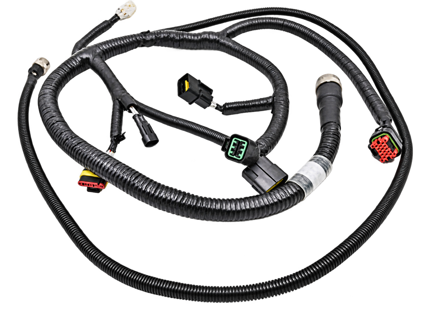
XSD Harness manufactures custom wiring harnesses for applications exposed to moisture, splash, dust, washdown, or other environmental conditions. Harnesses are built according to customer-approved drawings, connector systems, cable specifications, sealing methods, routing, and validation requirements.
Specify the environment and acceptance criteria with your drawing.
DESIGNED AROUND THE ENVIRONMENT
A waterproof wiring harness is designed to reduce water or moisture ingress at vulnerable interfaces such as connectors, cable entries, splices, branches, and terminations. The sealing method depends on the application, connector system, cable construction, installation method and target ingress-protection level.
Waterproof performance is determined by the complete harness design and validation method. A molded or sealed component alone does not automatically make the entire harness IP67 or IP68.
| Term | Practical meaning |
|---|---|
| Water-resistant | Designed to tolerate limited moisture, splash or condensation. |
| Weather-resistant | Designed for specified outdoor moisture, dust, UV or temperature exposure, depending on materials. |
| Waterproof / IP-rated | Requires defined ingress criteria and validation of the final assembly. |
| Sealed harness | Uses sealing elements at connectors, joints, cable entries or branches. |
Select the category through the operating environment and validation standard rather than marketing terminology alone.
SPECIFY THE TESTED ASSEMBLY
An IP code describes protection against solid and water ingress. Select a code to see what must be defined.
IP67 combines dust-tight protection with temporary immersion under defined test conditions.
Specify the final assembly, mating state, installation and temporary-immersion test conditions.
Apply the rating to the tested final assembly and its defined interface conditions, not only to one connector. For IP68, agree the immersion depth or pressure and duration; the code does not provide one universal operating limit.
IP-code reference: IEC 60529.
Configurations are reviewed against the specified environment, components, sealing route and acceptance criteria.
Sealed connectors, wire seals, boots or molded protection for defined vehicle locations.
Connectorized connections for sensors, switches, encoders and field-mounted devices.
Machinery, automation and control assemblies for specified moisture or washdown exposure.
Agricultural, construction, lighting and exposed equipment connections.
Molded cable/connector transitions where integrated protection and sealing are specified.
Sealed panel interfaces or bulkhead connectors matched to the enclosure design.
Multi-branch layouts with approved junction, heat-shrink, molding or sealing methods.
Selected encapsulated assemblies with compatible components, compounds and process conditions.
INTERFACE BY INTERFACE
Match the sealing element to the interface it must protect.
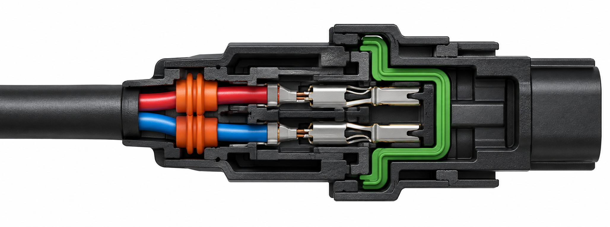
Use the approved housing, integrated seals, cable seals and gaskets as one connector system.
Include the seal specified by the approved connector design and confirm its assembly condition.
Use adhesive-lined or specified tubing around compatible transitions and splices.
Review injection-molded or low-pressure molded protection against the jacket and interface geometry.
Use only a confirmed process and compatible material for the particular project.
Define cable fit, panel sealing and installation requirements at enclosure boundaries.
Use for mechanical or environmental protection; sleeving and conduit alone do not establish waterproofing.
Molding provides a construction method; waterproofing defines the required performance. Explore Molded Wiring Harness construction.
The company profile documents production and inspection resources that support project-specific sealing designs.
Selected connector transitions and protective cable features.
Selected encapsulation and protective applications.
Project-specific sealing or encapsulation with suitable material and curing conditions.
Automatic/semi-automatic terminal processing and integration of connectors, boots, heat shrink, labels and conduit.
Electrical, dimensional, mechanical, salt-spray, bending and tensile resources for the approved quality plan.
FOLLOW THE COMPLETE SEALING PATH
Select an interface in the harness diagram to review what it contributes to the seal.
SEALING BOUNDARY
Review the housing, terminal seals, wire seals, mating part and unused-cavity closure as one approved system.
Define: part numbers, mating condition and assembly requirements.
A waterproof harness depends on the connector, terminal and wire seals, cable jacket, heat shrink, molding, branch construction, panel interface and installation. Failure at any one interface can compromise overall sealing.
Define the target environment and validation method during quotation rather than choosing sealing components in isolation.
XSD can manufacture harnesses around customer-specified waterproof connector systems, subject to component sourcing and process compatibility.
Provide housing, contact, seal and mating-part references. Connector appearance or a component rating does not establish the finished harness rating.
M8/M12, waterproof USB, RF/coax and sealed D-sub systems require a specific sourcing and compatibility review before availability or a product rating is confirmed.
Match moisture, oil, temperature, flexibility, UV and chemical exposure requirements.
Standard or adhesive-lined material as specified for the interface.
Mechanical protection along routed harness sections.
Abrasion and routing protection where required; not inherently waterproof.
PVC, rubber or project-defined tubing where appropriate.
Cable-entry protection with a defined fit and support profile.
Water-resistant label materials and identification where required.
Mechanical protection and waterproofing serve different functions. Confirm both in the approved specification.
TURN THE ENVIRONMENT INTO A SPECIFICATION
Describe actual exposure, installation and acceptance conditions.
Review environment, drawing, connector, cable, seal design, IP requirement, quantity and inspection criteria.
Cut, strip, crimp, solder or prepare conductors to the approved specification.
Install housings, terminal and wire seals, gaskets, boots and related sealing elements.
Route branches, sleeves, conduit, labels and other specified components.
Apply approved heat shrink, molding, low-pressure encapsulation, dispensing or protection.
Check sealing interfaces, connector assembly, dimensions and electrical function.
Where required, carry out or arrange the specified ingress or environmental validation method.
Keep manufacturing inspection and water-ingress validation clearly defined.
DOCUMENTED XSD RESOURCES
PROJECT-SPECIFIC REQUIREMENTS
The agreed plan may include splash, water spray, immersion, pressure-related ingress, leak testing, post-test continuity and insulation/electrical checks.
Define method, conditions, duration and acceptance criteria for the specific project. Where testing is not performed in-house, customer-approved external validation can be arranged if required.
Salt-spray and mechanical tests do not replace an ingress test. Mating and installation conditions belong in the validation plan.
Sealing requirements vary by location, temperature, vibration, chemicals, connector system and exposure. XSD manufactures to customer-defined component and validation requirements rather than one universal waterproof specification.
Dust, moisture, movement and outdoor exposure need to be reviewed together.
Specify the exposed routes, connector locations, cleaning method and environmental limits. Protective construction and sealing should suit the equipment installation and service conditions.
Field connections may need sealing as well as controlled routing and strain relief. Review the actual cleaning, movement and enclosure conditions.
Circular sensor interfaces are reviewed to the specified connector system; M8/M12 availability is confirmed for the project.
Customer drawings, sealing requirements and connector specifications guide the build.
Vertical injection and low-pressure molding support selected protection designs.
Direct wire and cable manufacturing experience supports construction review.
Heat shrink, sleeving, molding, dispensing and sealed connector integration where specified.
Electrical, dimensional, mechanical and selected environmental test equipment.
Development builds and approved samples support repeat production.
Send your available information so the review can identify the details still needed.
A coordinated sealing design protects the connector interfaces, wire entries, splices, branches, terminations and enclosure interfaces that are exposed. The final assembly needs defined conditions and acceptance criteria; one sealed component is not enough to establish the harness rating.
XSD can review projects with IP67 or IP68 requirements. The required rating, installation state, mating interfaces and test conditions must be defined and validated for the complete final assembly.
Customer-specified waterproof connector systems can be reviewed, subject to sourcing and assembly/process compatibility. Provide the housing, terminal, seal and mating part numbers rather than selecting by appearance alone.
Yes, selected constructions can use molded connector transitions or low-pressure molded protection. Material adhesion, jacket compatibility, connector seals and the complete validation plan determine whether the interface meets the specified ingress requirement.
Waterproof describes an environmental performance requirement. Overmolding describes a manufacturing process that adds a molded layer to an existing interface. A waterproof harness may use overmolding, but an overmolded harness is not automatically waterproof.
Specified heat shrink and boots can be integrated where they suit the cable, connector and installation. Define the material, coverage, application conditions and required acceptance checks during review.
The company profile documents electrical, dimensional, mechanical, salt-spray and other inspection resources; it does not establish a universal in-house immersion capability. The project specifies the ingress test method, conditions and acceptance criteria. Customer-approved external validation can be arranged if required.
A sample can support the review, together with a drawing, BOM, connector references and sealing requirements. Confirm the electrical circuit, dimensions, materials and validation criteria before repeat manufacturing.
Prototype and development quantities can be reviewed before repeat production. Confirm components, tooling if required, sample quantity, validation responsibilities and approval criteria during quotation.
Send the drawing, BOM, connector and cable references, branch layout, sealing method, environment, target IP requirement if applicable, depth or pressure, duration, quantity and inspection criteria. A physical sample is useful where available.
Share the drawing, connector and sealing references, exposure conditions and validation needs. XSD will review the complete assembly with your application requirements.