Molded Connector Wiring Harnesses
Molded protection around the cable-to-connector transition, with controlled cable entry and interface support.
CUSTOM WIRING HARNESS / MOLDED
The harness. The molded features.
One integrated assembly.
XSD Harness manufactures custom wiring harnesses with molded connector transitions, strain relief, encapsulation, or protective molded features according to customer drawings, cable specifications, connector requirements, mold geometry, and inspection criteria.
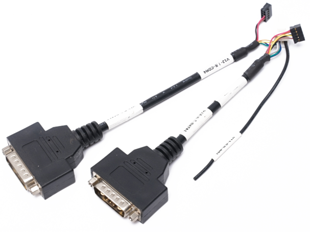
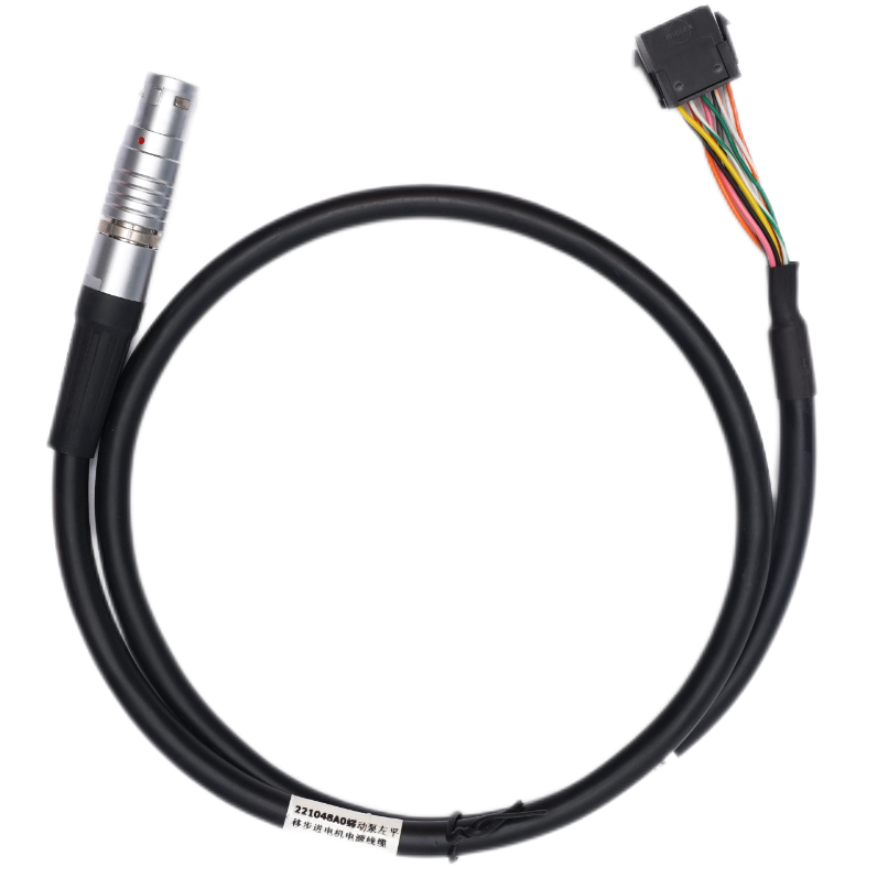
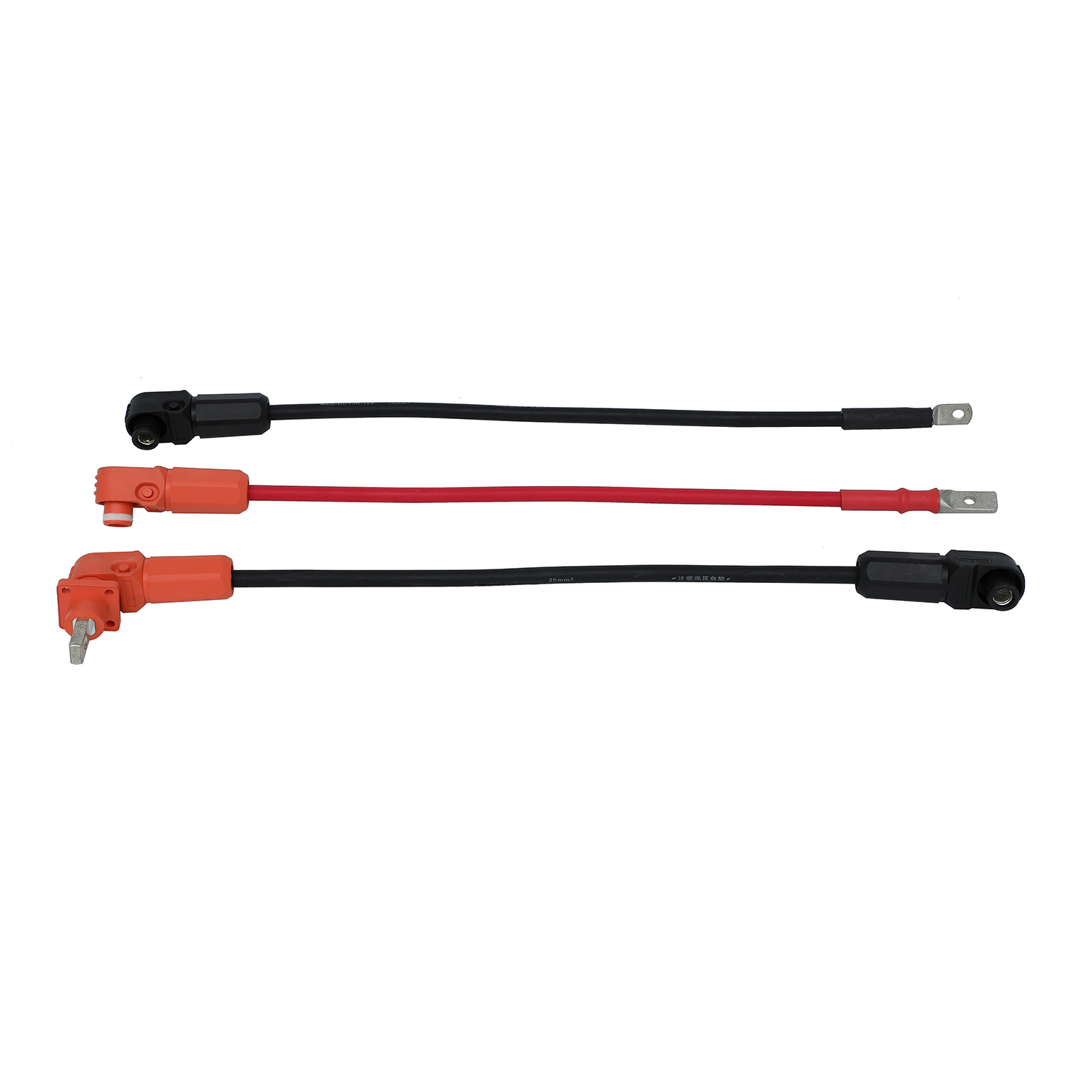
Connectorized assembly examples
THE FINISHED ASSEMBLY
A molded wiring harness incorporates molded material around selected cable, connector, branch, or component areas to create an integrated mechanical structure. Depending on the design, molding may provide strain relief, insulation, connector stabilization, component encapsulation, cable-entry reinforcement, or environmental protection.
Molding alone does not automatically guarantee a specific waterproof, IP, chemical, or temperature rating. Final performance depends on the complete design, materials, interfaces, molding process, and validation requirements.
Start with the finished harness architecture, then define the purpose and location of each molded section. Configurations below are reviewed against the project drawing and confirmed process compatibility.
Molded protection around the cable-to-connector transition, with controlled cable entry and interface support.
Molded junction areas for a defined multi-branch routing layout. Branch geometry and tooling require project review.
Connectorized assemblies with integrated strain relief for specified sensors and electronic devices.
Selected cable transitions or component areas protected by compatible low-pressure encapsulation.
Power-oriented assemblies with molded protection at specified terminals or connector interfaces.
Signal and control connections using molded features for stabilization and strain relief.
Customer-specified circular systems, including M8 or M12 only after component and molding compatibility are confirmed.
Project-defined features around cable entries, switches, sensors and other specified interfaces.
Have a molded part drawing or sample?
Share the harness layout and molded-area requirements for review.
The finished harness and the process used to protect it are related, but they answer different design questions.
| Process | Typical purpose | Project focus |
|---|---|---|
| Molding | Create an integrated feature or housing around part of a harness. | Finished harness architecture and molded-feature integration. |
| Overmolding | Add a protective molded layer around an existing cable or connector interface. | Transition geometry, material adhesion and the molding process. |
| Low-Pressure Molding | Encapsulate selected sensitive components at lower molding pressure. | Confirm component, process and compound compatibility. |
| Potting / Dispensing | Fill or encapsulate a cavity with a resin or compound. | UV dispensing is documented; a specific potting route is confirmed for the project. |
For a process-led overmolding project, discuss your overmolded wiring harness requirements. This page covers the completed harness, molded branches, connector integration and tooling geometry.
EQUIPMENT & PROCESS
Documented production resources support the review of selected cable, connector, branch and component applications.
For selected cable and connector operations requiring vertical tool access and controlled part positioning.
For selected encapsulation and protection processes where lower molding pressure is appropriate.
For compatible project-specific dispensing or encapsulation applications with a defined cure method.
Custom mold geometry: Dedicated profiles are reviewed against part geometry, cable position, material, production quantity and approval requirements. Equipment availability does not establish compatibility with every connector or molded shape.
The underlying electrical assembly, mold and material are reviewed together before repeat production.
Review the wiring diagram, BOM, connector part numbers, cable specification, molded geometry, target function, quantity and inspection criteria.
Cut, strip, crimp, insert, solder where specified, and assemble the underlying harness before molding.
Confirm cavity geometry, part positioning, cable exit angle, strain-relief profile and tooling requirements.
Select the compound and process against application requirements and verified interface compatibility.
Perform vertical injection molding or low-pressure molding according to the approved process.
Trim flash, inspect surfaces, and add labels or secondary protection where the drawing requires them.
Perform project-defined visual, dimensional, mechanical and electrical checks.
Prepare the electrical assembly first.
Wire preparation, terminal processing and connector assembly establish the circuit and part positions that the molded feature must support.
EXPLORE THE INTEGRATION
Select a feature to see the design considerations. Geometry is illustrative; the approved drawing defines the finished assembly.
 Design schematic
Molded connector transitions can combine cable-entry reinforcement, an exit boot, strain relief and terminal-transition protection. Define the support length, cable exit direction and mating clearances.
A molded Y-split can stabilize the branch region and define cable exit positions. Review the electrical connection, branch lengths, junction envelope and cable retention before tooling.
Selected sensor or switch bodies, PCBs and small components may be protected using low-pressure molding or another confirmed encapsulation route. Review heat, pressure, compound and cure compatibility.
Choose the compound for the interface and service conditions, then verify its compatibility with the cable jacket and connector body.
Review for strain relief and cable flexibility, with the required hardness and mechanical behavior.
Review for selected encapsulation and component-protection applications.
Customer-designated compounds are assessed for sourcing and process compatibility.
General wire-insulation materials do not establish the available molding-compound range. The exact compound is confirmed during review.
Sealing depends on the complete interface.
Molded construction can help improve sealing around cable and connector transitions. Performance depends on interface design, material adhesion, connector seals, the cable jacket, mold geometry and validation method.
If an IP67, IP68, immersion, washdown or other sealing requirement applies, specify it during project review and validate it against the final assembly design.
Reduce concentrated bending at the cable-to-connector transition through a suitable support profile.
Mechanically support the cable and connector interface within the approved layout.
Define the bend-support geometry for the specified installation and movement.
Add material around vulnerable cable-entry regions where the design requires it.
Combine features that may otherwise need separate boots, sleeves or mechanical components.
Durability is evaluated for the actual load, movement and environment. A molded feature does not by itself establish a universal service-life improvement.
FROM GEOMETRY TO APPROVAL
Custom molded harness projects may require dedicated tooling. Requirements depend on connector geometry, molded profile, cable position, quantity, material and whether a new or confirmed existing mold configuration is suitable. Establish tooling scope and sample approval before production release.
Evaluate both the electrical harness and the molded feature.
Flash, voids, incomplete fill, visible damage, cable position and mold-to-cable transitions.
Molded geometry, cable exit position, key dimensions and connector location.
Tensile / pull force, connector retention and bending evaluation where required.
Circuit verification, DC resistance and harness testing where applicable.
XSD’s documented inspection resources also include salt-spray and plug/pull testing. Inspection methods and sampling requirements follow the customer-approved drawing, molding specification, connector requirements and quality plan.
Configure the molded feature around the installation, routing and service conditions.
Sensors, actuators, motors, control devices and machine interfaces.
Selected electronic, sensor, lighting and vehicle equipment connections.
Compact, strain-relieved connections in moving or space-constrained equipment.
Connectorized harnesses with controlled routing and clean mechanical integration.
Defined power, signal and control interfaces inside storage equipment.
Integrated cable connections where molding supports mechanical packaging.
Tooling confirmation and sample trials form part of the approval route.
Confirm sample quantity, component availability, tooling scope, lead time and acceptance criteria during quotation. Document approved changes before repeat production.
Send the details you have now. The review can identify what is still needed.
A molded harness describes the finished assembly with integrated molded features. Overmolding describes adding a molded layer around an existing cable, connector or component. A finished molded harness may use an overmolding process; this page focuses on the overall harness architecture and integrated features.
XSD reviews custom connector harnesses against the drawing, connector part numbers, cable specification, molded profile, tooling and inspection requirements. Component and process compatibility are confirmed before a production construction is agreed.
The company profile documents a 2.5T vertical injection molding machine, a low-pressure injection molding machine and UV dispensing equipment. The applicable route depends on the part geometry, materials, interfaces and protection function.
Yes. Documented low-pressure injection molding equipment supports review of selected component encapsulation and cable-transition projects. Pressure, temperature, material and component compatibility must suit the proposed assembly.
Project-defined molded shapes, cable positions and straight or angled exits can be reviewed. Feasibility depends on the connector geometry, available space, mold release, material and tooling requirements.
They can be designed for sealing, but molding alone does not establish a waterproof rating. Specify the IP, immersion, washdown or other requirement and the validation method so the final cable, connector and molded interface can be assessed together.
Material selection considers flexibility, hardness, adhesion, operating temperature, chemicals, flame requirements and compatibility with the cable jacket and connector body. Flexible thermoplastics, low-pressure compounds and customer-specified materials are reviewed for the particular project.
Some projects need a dedicated mold; others may use a confirmed existing configuration. The molded profile, connector, cable positioning, material and production quantity determine the tooling review and sample approval route.
A sample can support the review, preferably together with drawings, the BOM and electrical requirements. Dimensions, material, pinout, connector references and acceptance criteria still need approval before repeat manufacturing.
Available resources include harness and DC resistance testing, CCD inspection, dimensional measurement, tensile, bending, salt-spray and plug/pull testing. Checks and sampling are selected according to the approved drawing, molding specification, connector requirements and quality plan.
Prototype and sample projects can be reviewed before repeat production. Confirm quantity, component sourcing, tooling cost, sample trials, first-article requirements and production release criteria during quotation.
Share the harness drawing, connector references and molded-area requirements. XSD will review the assembly, material, tooling route and inspection needs.