Battery-to-Battery Cables
Interconnections between battery modules or packs in a customer-defined series or parallel architecture. Terminal interfaces and polarity follow the approved system drawing.
XSD Harness manufactures custom battery cable assemblies according to customer drawings, cable specifications, terminal requirements, dimensions, routing, and inspection criteria. Assemblies can be configured for battery-to-battery, battery-to-inverter, battery-to-equipment, grounding, and other OEM power connections.
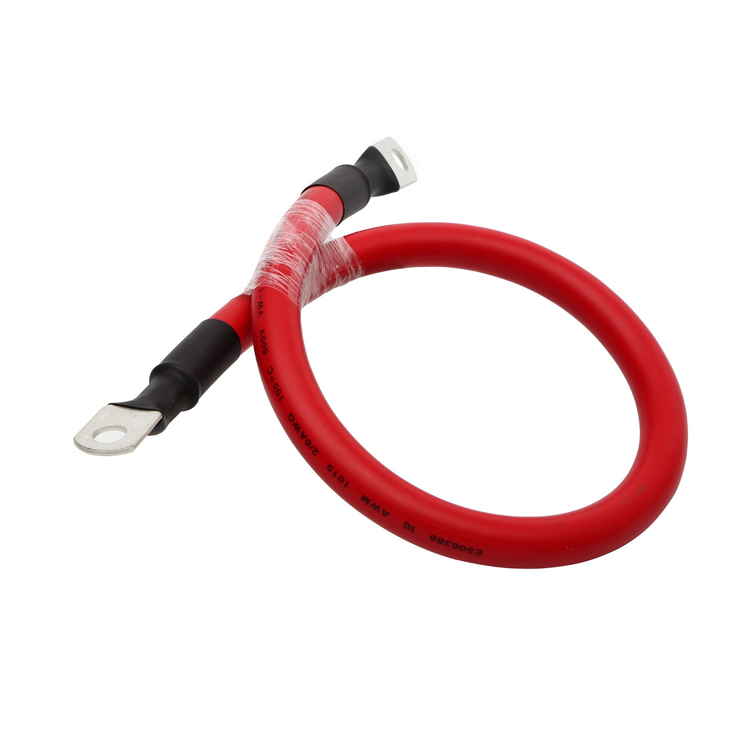
A battery cable assembly provides a low-resistance electrical connection between a battery and another part of the power system, such as a starter, inverter, power distribution unit, charging system, equipment or another battery module. Related assemblies can also serve specified auxiliary and battery-management connections.
The finished assembly is defined by its cable size, conductor construction, terminals, length, polarity, insulation, protection and routing—not simply by its appearance. XSD manufactures to the approved electrical, mechanical and inspection requirements for the application.
Choose the connection architecture first, then define the cable and both end interfaces.
Interconnections between battery modules or packs in a customer-defined series or parallel architecture. Terminal interfaces and polarity follow the approved system drawing.
Power connections between batteries and inverters or other power electronics. Cable size, length and terminal requirements are reviewed against the operating conditions.
Battery power connections for industrial equipment, vehicles and electrical systems, with the required connector or bolted termination.
Connections from the battery negative terminal to chassis or a defined ground point. Routing, mounting interfaces and contact requirements are specified by the customer.
Single- or double-ended lug assemblies for bolted connections. Define stud-hole dimensions, lug part numbers, cable size and terminal orientation.
Mixed connector and terminal interfaces that connect specified components. Supply both mating interfaces and circuit or polarity information.
Custom lengths for installation distances between batteries and equipment. Voltage-drop and routing requirements are reviewed before production.
Multiple power connections within a customer-defined architecture. Branch lengths, connection method, protection and circuit assignments require an approved drawing.
Control the details that determine fit, routing and connection quality. The approved drawing and BOM establish the production configuration.
| Option | Specification / choices |
|---|---|
| Cable size | Selected for the electrical and mechanical requirements |
| Conductor | Customer-specified copper construction |
| Cable length | Custom overall length and drawing tolerances |
| Terminal | Ring, fork, stud connection, connector or specified interface |
| Terminal orientation | Defined for installation and mating geometry |
| Polarity / color | Red, black or project-specified identification |
| Insulation | According to the approved cable specification |
| Heat shrink | Standard or adhesive-lined construction as specified |
| Protection | Tube, conduit, braid or specified protective material |
| Terminal boots | Where required and compatible with the interface |
| Branches | Single-cable or multi-branch construction |
| Labels | Part number, circuit or other approved identification |
| Overmolding | Subject to material, tooling and design compatibility |
| Packaging | Project-specific packing and identification |
Cable selection starts with the electrical load and installation conditions, not a universal ampacity figure.
Conductor construction selected for the required flexibility, routing and electrical performance.
Considered where specified by the customer and appropriate to the cable construction and environment.
Cable selected to the customer’s applicable automotive specification, temperature and installation requirements.
Construction matched to the specified battery, rack, inverter or cabinet connection.
Review current, voltage, conductor cross-section, insulation, operating temperature, flexibility, routing and environment together. Current capability also depends on ambient temperature, bundling, duty cycle, allowable voltage drop, installation and the applicable standard. High-voltage cable requires an additional insulation and interface review.
Bolted interfaces defined by lug part number, barrel dimensions, cable compatibility and stud-hole size.
Used where specified and suitable for the customer’s mounting interface.
Specified connector systems matched to the cable, contact and mating component.
Different end interfaces on one assembly, with controlled orientation and polarity.
Bare or plated copper terminals are evaluated against specification, environment, corrosion requirements and component availability. Tinned terminals are not assumed for every design.
Review current, voltage, cable specification, terminal part numbers, dimensions, routing, environment, quantity and inspection requirements.
Cut and strip to the approved dimensions. Match the process to conductor construction and insulation without damaging strands.
Use the specified terminal and a compatible tooling/process combination. Establish compression and inspection requirements for the connection.
Apply approved heat shrink, boots, sleeving, conduit and labels. Confirm placement and orientation against the drawing.
Arrange cables, branches and related components to the approved layout, with defined lengths and installation references.
Check the finished assembly against the quality plan, document required results and pack according to the project requirements.
Equipment shown is from the company profile. The processing route and tooling are confirmed for the selected cable and terminal.
A reliable connection depends on a matched conductor, terminal and crimp process.
Review the cable size and strand construction, terminal barrel geometry, strip dimensions, tooling and compression requirements as one connection system. A terminal that fits over a conductor is not by itself proof of an acceptable crimp.
XSD’s documented resources include automatic and semi-automatic terminal processing, tensile testing and applicable cross-section inspection. The quality plan defines which checks apply to the chosen connection; dedicated heavy-lug tooling or a specific cable-size capacity is confirmed during review.
Insulation and identification at specified locations. Adhesive-lined material can be reviewed when requested.
Protective covers matched to the terminal geometry and installation clearances.
Abrasion and routing protection selected for the application environment.
Selected strain-relief or protective features subject to materials, tooling and design review.
Specify coverage length, material, temperature and installation conditions. Protection features do not automatically establish a waterproof rating. Any sealing requirement needs defined acceptance criteria and validation.
High-voltage battery cable projects are reviewed against the customer drawing, cable and connector specifications, system voltage, insulation, shielding, routing, safety and inspection requirements. Provide the operating conditions and the required validation plan before selecting a construction.
A point-to-point battery cable is distinct from a complex high-voltage wiring harness. Harness projects with additional circuits, shielding terminations or high-voltage interlock requirements need a broader system-level review.
Custom connections can support battery modules, racks, inverters, busbars, cabinet power and grounding. Related BMS auxiliary connections and station-level interfaces are defined separately within the approved system architecture.
Send the interface drawings, cable specification, operating current, system voltage, routing space and inspection criteria. Each assembly is manufactured for the specified connection rather than treated as a universal storage-system cable.
Applications include starter, alternator, chassis ground, battery distribution, auxiliary equipment and vehicle power connections. EV low-voltage auxiliary connections can also be reviewed against the specified vehicle architecture.
Provide mounting points, routing, vibration and temperature requirements, service clearances and terminal orientation. High-voltage traction connections require a separate high-voltage harness or cable review.
Build-to-print power connections can be configured for forklifts, agricultural and construction machinery, robotics, mobile equipment, backup power and industrial battery packs.
The installation environment determines the necessary flexibility, abrasion protection, termination arrangement and inspection plan. Define moving routes, mounting constraints and service conditions so these requirements can be reviewed before sample production.
Overall and branch lengths, strip dimensions, terminal orientation, protection placement and labels.
Crimp evaluation, pull force where applicable and specified terminal or connector retention.
Continuity, circuit verification and DC resistance where required by the approved specification.
Relevant salt-spray, bending or other project-specific checks with agreed methods and acceptance criteria.
Testing methods and acceptance criteria are selected according to the approved cable, terminal, drawing, and customer inspection requirements.
Voltage drop depends on cable size, length, current, material, temperature and connection resistance. Provide operating current and allowable limits for review; no universal voltage-drop guarantee is assumed.
XSD Harness is supported by the wire and cable manufacturing background of Dongguan XSD Cable Technology Co., Ltd.
Direct experience with conductor, insulation and application-specific cable requirements supports technical review.
Manufacturing based on the approved drawing, BOM, dimensions and inspection requirements.
Connection methods selected for the specified cable, terminal and applicable tooling.
Compatible protective processing integrated where the design requires it.
Electrical, dimensional and mechanical checks selected through the project quality plan.
Sample approval and documented requirements support repeat OEM production.
Confirm component availability, tooling, sample quantity, lead time and approval criteria during quotation. Approved changes are documented before subsequent production.
Send the information available now; the project review can identify the details still needed.
Yes. Send the drawing or sample with the cable, terminal and application requirements. A sample helps clarify geometry, but hidden requirements such as material, operating current and acceptance criteria still need confirmation. Production follows the agreed specification.
Cable size is reviewed with conductor construction, terminal compatibility, tooling and inspection requirements. Send your required cross-section or cable part number for confirmation. We do not apply a single published size range to every cable and termination combination.
Yes. Include the cable specification, lug or terminal part numbers, mating interface and approved sourcing requirements. Any proposed substitution needs customer approval before manufacture.
Battery-to-inverter assemblies can be reviewed for your system. Provide operating current, system voltage, length, terminal details, routing, temperature and inspection criteria so that the complete connection can be evaluated.
Yes. Overall length, branch lengths and terminal orientation are defined on the approved drawing. Specify measurement reference points, tolerances and the relative angle between end terminals.
These features can be included where compatible with the selected components and process. Identify the required material, covered length and location. Sealing or environmental requirements need a defined design and validation plan.
High-voltage projects are reviewed according to cable, connector, voltage, insulation, shielding and inspection requirements. Complex high-voltage harnesses, including interlock circuits where required, need a separate system-level review.
Checks may include visual and dimensional inspection, crimp evaluation, applicable pull-force testing, continuity and DC resistance where required. Environmental or durability checks are selected from the agreed specification and available resources.
Yes. Battery module, rack, inverter, cabinet and grounding connections can be reviewed. Supply the architecture, interface details, cable requirements and electrical acceptance criteria for the proposed energy storage application.
Yes. Sample and first-article builds can be reviewed before repeat production. Component availability, tooling, quantity, lead time and the approval process are agreed during quotation rather than assumed for every project.
Share your drawing, cable requirements and terminal details. XSD will review the connection, manufacturing route and inspection needs for your application.